
Users Manual Part 1

23
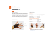
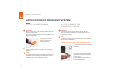
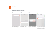
2. Plug the other end of the USB
cable into the Micro USB socket of
the Gateway. A clear clicking sound
GSRƼVQWXLIGSVVIGXJEWXIRMRK
RESULT
The LED of the Access Point lights up green. The boot up
of the Gateway takes around 2min until the LED 1 lights
up green. The connectivity device is connected to the end
device.
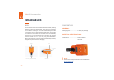
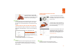
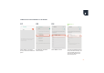
CONNECTION WITH USB CABLE IN USB CDC MODE:
*SPPS[XLITVIZMSYWWXITERHWXITJSVƈ'SRRIXMSR[MXL
97&'EFPIMR97&,-(1SHIƉ'SRXMRYI[MXLXLIJSPPS[MRK
steps:
-RXLIGSRƼKYVEXMSRXSSP
(https://insight.proglove.com/) under
ƈ'SRRIGXMZMX]'SRƼKYVEXMSR"-RXI-
gration Path” select USB CDC. More
detailed information about this can be
JSYRHMRGLETXIVƈ'SRƼKYVIHIZMGIWERH
ƼVQ[EVIYTHEXIƉ
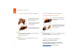
4. Connect with the COM port on the end device.
RESULT
The LED of the Access Point lights up green. The boot
up of the Gateway takes around 2min until the LED 1
lights up green. The connectivity device is connected to
the end device.
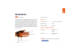
CONNECTION WITH RS232 CABLE VIA
ACCESS POINT
1. Connect the RS232 cable with the
end device. Connect the power supply
to the RS232 cable and into an external
power source.
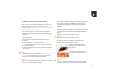
2. Plug the other end of the RS232 ca-
ble into the RJ50 socket of the Access
4SMRX%GPIEVGPMGOMRKWSYRHGSRƼVQW
the correct fastening.
3. Check which baud rate must be set.
The baud rate is set to 115,200 as a
standard. At a different baud rate, this
MWXSFIWIXMRXLIGSRƼKYVEXMSRXSSP
GSRƼKTVSKPSZIHI.
4. Select the COM port on the end
device and set the appropriate baud
rate.
RESULT
The LED of the Access Point lights up green.
The Access Point is connected to the end device.