
Users Manual Part 1

13
The Access Point receives the scanned barcode data from the
scanner via 868/915 MHz. This barcode data is transmitted to the
IRHHIZMGIZME97&GEFPISV67GEFPI-RXLI97&,-(QSHIXLI
Access Point simulates a computer keyboard. A serial connection is
IQYPEXIHMRXLI97&'('QSHI-RSVHIVXSYWIXLI97&'('QSHI
the device must be set to “USB CDC” in the configuration tool (config.
proglove.de) under “Device settings - Output mode”.
A RS232 cable establishes a serial connection between Access Point
and the end device.
The Gateway receives the scanned barcode data from the scanner
via BLE. This barcode data is transmitted to the end device via USB
GEFPI -R XLI 97& ,-( QSHI XLI +EXI[E] WMQYPEXIW E GSQTYXIV
OI]FSEVH%WIVMEPGSRRIGXMSRMWIQYPEXIHMRXLI97&'('QSHI-R
order to use the USB CDC mode, the device must be set to “USB CDC”
MR XLI 4VS+PSZI-RWMKLX 'SRJMKYVEXMSR8SSP (https://insight.proglove.
com/) YRHIV ƈ'SRRIGXMZMX] 'SRJMKYVEXMSR -RXIKVEXMSR TEXLƉ Also
multipairing is possible. The Gateway can be connected with up to 5
scanners simultaneously.
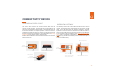
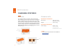
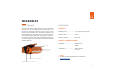
CONNECTIVITY DEVICE
3:)6:-);%'')7743-28
Label with serial number
LED
Pairing
Barcode
Cable release
opening
RJ50 socket
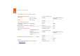
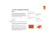
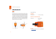
3:)6:-);+%8);%=
Pairing
Barcode
•LED 1 (USB LED)
•LED 2 (Scanner LED)
•LED 3 (Cloud LED)
Label with serial number
Micro USB socket