Model No. PETL10714.0 Serial No. Write the serial number in the space above for reference. USER’S MANUAL Serial Number Decal CUSTOMER SERVICE UNITED KINGDOM Call: 08457 089 009 From Ireland: 053 92 36102 Website: www.iconsupport.eu E-mail: csuk@iconeurope.com Write: ICON Health & Fitness, Ltd. c/o HI Group PLC Express Way CASTLEFORD WF10 5QJ UNITED KINGDOM AUSTRALIA Call: 1800 993 770 E-mail: australiacc@iconfitness.
TABLE OF CONTENTS WARNING DECAL PLACEMENT . . . . . . . . . . . . . . . . . . . . . . . . . . . . . . . . . . . . . . . . . . . . . . . . . . . . . . . . . . . . . . .2 IMPORTANT PRECAUTIONS. . . . . . . . . . . . . . . . . . . . . . . . . . . . . . . . . . . . . . . . . . . . . . . . . . . . . . . . . . . . . . . . . . 3 BEFORE YOU BEGIN. . . . . . . . . . . . . . . . . . . . . . . . . . . . . . . . . . . . . . . . . . . . . . . . . . . . . . . . . . . . . . . . . . . . . . . .5 PART IDENTIFICATION CHART.
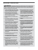
IMPORTANT PRECAUTIONS WARNING: To reduce the risk of burns, fire, electric shock, or injury to persons, read all important precautions and instructions in this manual and all warnings on your treadmill before using your treadmill. ICON assumes no responsibility for personal injury or property damage sustained by or through the use of this product. 1. It is the responsibility of the owner to ensure that all users of this treadmill are adequately informed of all warnings and precautions. 12.
21. Do not attempt to move the treadmill until it is properly assembled. (See ASSEMBLY on page 7 and HOW TO FOLD AND MOVE THE TREADMILL on page 25.) You must be able to safely lift 45 lbs. (20 kg) to move the treadmill. 26. 22. When folding or moving the treadmill, make sure that the storage latch is holding the frame securely in the storage position. 23. Do not change the incline of the treadmill by placing objects under the treadmill.
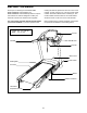
BEFORE YOU BEGIN Thank you for selecting the new PROFORM® PERFORMANCE 1050 treadmill. The PERFORMANCE 1050 treadmill provides an impressive selection of features designed to make your workouts at home more effective and enjoyable. reading this manual, please see the front cover of this manual. To help us assist you, note the product model number and serial number before contacting us. The model number and the location of the serial number decal are shown on the front cover of this manual.
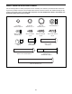
PART IDENTIFICATION CHART Use the drawings below to identify small parts used for assembly. The number in parentheses below each drawing is the key number of the part, from the PART LIST near the end of this manual. The number following the key number is the quantity used for assembly. Note: If a part is not in the hardware kit, check to see whether it is preattached. Extra parts may be included.
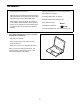
ASSEMBLY • Assembly requires two persons. • Left parts are marked “L” or “Left” and right parts are marked “R” or “Right.” • Place all parts in a cleared area and remove the packing materials. Do not dispose of the packing materials until you finish all assembly steps. • To identify small parts, see page 6. • Assembly requires the following tools: • After shipping, there may be an oily substance on the exterior of the treadmill. This is normal.
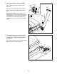
2. Make sure that the power cord is unplugged. 2 Press a Base Cap (74) into each side of the Base (85). Wire Tie 81 81 Identify the Right Upright (90). Have a second person hold the Right Upright near the Base (85). 90 See the inset drawing. Tie the wire tie in the Right Upright (90) securely around the end of the Upright Wire (81). Then, insert the Upright Wire into the lower end of the Right Upright as you pull the other end of the wire tie out of the Right Upright. Wire Tie 74 74 90 85 3.
4. Hold the Right Upright (90) against the Base (85). Be careful not to pinch the wires. Partially tighten three 3/8" x 4" Screws (7) with three 3/8" Star Washers (13) into the Right Upright and the Base; do not fully tighten the Screws yet. 4 90 Attach the Left Upright (not shown) in the same way. Note: There are no wires on the left side. 13 7 Wires 85 5. Identify the Left and Right Base Covers (82, 83). Slide the Left and Right Base Covers onto the Left and Right Uprights (89, 90) as shown.
6 . Set a Handrail (84) onto the Right Upright (90). Make sure that the Upright Wire (81) is not pinched. 6 28 Attach the Handrail (84) with two 5/16" x 2 1/4" Screws (28) and two 5/16" Star Washers (11). Start both Screws, and then tighten them. 11 84 Attach the other Handrail (not shown) in the same way. Note: There is no wire on the left side. 81 Remove and discard the two indicated screws (A) from both Handrails (84) (only one side is shown). 7.
8. With the help of a second person, hold the console assembly near the right Handrail (84) and the left Handrail (not shown). 8 Console Assembly See the inset drawing. Connect the Upright Wire (81) to the console wire. The connectors should slide together easily and snap into place. If they do not, turn one connector and try again. IF YOU DO NOT CONNECT THE CONNECTORS PROPERLY, THE CONSOLE MAY BECOME DAMAGED WHEN YOU TURN ON THE POWER. Then, remove the wire tie from the Upright Wire.
10. I MPORTANT: To avoid damaging the Pulse Crossbar (5), do not use power tools and do not overtighten the #10 x 3/4" Screws (9). 10 Tighten four #10 x 3/4" Screws (9) with four 1/4" Star Washers (26) into the Pulse Crossbar (5) and the Handrails (84). Start all four Screws, and then tighten them. 9 26 See step 9. Tighten the four 1/4" x 1/2" Screws (2). 84 5 Console Assembly 9 26 84 11. Identify the Left and Right Handrail Inserts (79, 31).
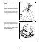
12. Identify the Left and Right Handrail Covers (87, 8). 12 Console Assembly Slide the Left Handrail Cover (87) up against the console assembly and tighten a #8 x 3/4" Screw (4) into the bottom of the Left Handrail Cover. Be careful not to overtighten the Screw. 87 Attach the Right Handrail Cover (8) in the same way. 4 8 4 13 . Note: If it is assembled on a smooth surface, the treadmill may roll forward during this step. 13 Raise the Frame (56) to the upright position.
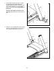
. Orient the Storage Latch (96) so that the decals are facing away from the treadmill as shown. 14 Tie Attach the lower end of the Storage Latch (96) to the bracket on the Base (85) with a 5/16" x 1 3/4" Bolt (94), two Latch Spacers (98), and a 5/16" Nut (34) as shown. Raise the Storage Latch (96) to a vertical position. Then, remove the tie from the top of the Storage Latch. 96 Decals 34 98 15.
16. Firmly tighten all six 3/8" x 4" Screws (7). Then, slide the Left and Right Base Covers (82, 83) downward. 16 82 7 83 7 17. Make sure that all parts are properly tightened before you use the treadmill. If there are sheets of plastic on the treadmill decals, remove the plastic. To protect the floor or carpet, place a mat under the treadmill. To avoid damage to the console, keep the treadmill out of direct sunlight.
THE CHEST HEART RATE MONITOR HOW TO PUT ON THE HEART RATE MONITOR The heart rate monitor consists of a chest strap and a sensor. Insert the tab on one end of the chest strap into the hole in one end of the sensor as shown. Then, press the end of the sensor under the buckle on the chest strap. The tab should be flush with the front of the sensor.
SP HOW TO USE THE TREADMILL HOW TO PLUG IN THE POWER CORD Follow the steps below to plug in the power cord. This product must be earthed. If it should malfunction or break down, earthing provides a path of least resistance for electric current to reduce the risk of electric shock. This product’s power cord has an equipment-earthing conductor and an earthing plug. IMPORTANT: If the power cord is damaged, it must be replaced with a manufacturer-recommended power cord. 1.
CONSOLE DIAGRAM FEATURES OF THE CONSOLE You can even listen to your favorite workout music or audio books with the console’s stereo sound system while you exercise. The treadmill console offers an impressive array of features designed to make your workouts more effective and enjoyable. When you use the manual mode, you can change the speed and incline of the treadmill with the touch of a button. As you exercise, the console will display instant exercise feedback.
HOW TO TURN ON THE POWER HOW TO USE THE MANUAL MODE IMPORTANT: If the treadmill has been exposed to cold temperatures, allow it to warm to room temperature before you turn on the power. If you do not do this, you may damage the console displays or other electrical components. 1. Insert the key into the console. Plug in the power cord (see page 17). Next, locate the power switch on the treadmill frame near the power cord. Press the power switch into the reset position.
5. Follow your progress with the displays. 6. Measure your heart rate if desired. The matrix—When you select the manual mode, the matrix will display a track that represents 400m (1/4 mile). As you exercise, the indicators around the track will appear in succession until the entire track appears. The track will then disappear and the indicators will again begin to appear in succession.
HOW TO USE AN ONBOARD WORKOUT The workout will continue in this way until the last segment of the profile flashes in the display and the last segment ends. The walking belt will then slow to a stop. 1. Insert the key into the console. See HOW TO TURN ON THE POWER on page 19. Note: The calorie goal is an estimate of the number of calories that you will burn during the workout. The actual number of calories that you burn will depend on various factors such as your weight.
HOW TO USE AN IFIT WORKOUT When you select an iFit workout, the display will show the name, duration, maximum speed setting, and distance of the workout. The display will also show the approximate number of calories you will burn during the workout and a profile of the speed settings of the workout. Note: To use an iFit workout, you must have an optional iFit module. To purchase an iFit module at any time, go to www.iFit.com or call the telephone number on the front cover of this manual.
HOW TO USE THE SOUND SYSTEM THE INFORMATION MODE To play music or audio books through the console sound system while you exercise, plug a 3.5 mm male to 3.5 mm male audio cable (not included) into the jack on the console and into a jack on your MP3 player, CD player, or other personal audio player; make sure that the audio cable is fully plugged in. Note: To purchase an audio cable, see your local electronics store.
MODULE—If an iFit module is connected, the display will show the word WIFI. If a USB module is connected, the display will show the word USB/SD. the network SSID, the network encryption type, the wireless signal strength, the IP address of the module, the number of registered users and their names, and the results of the DNS lookup. To return to the information mode, remove the key from the console and repeat the instructions near the beginning of this page.
HOW TO FOLD AND MOVE THE TREADMILL HOW TO FOLD THE TREADMILL HOW TO MOVE THE TREADMILL To avoid damaging the treadmill, adjust the incline to zero before you fold the treadmill. Then, remove the key and unplug the power cord. CAUTION: You must be able to safely lift 45 lbs. (20 kg) to raise, lower, or move the treadmill. Before moving the treadmill, fold it as described at the left. CAUTION: Make sure that the latch knob is locked in the storage position. Moving the treadmill may require two people. 1.
MAINTENANCE AND TROUBLESHOOTING MAINTENANCE SYMPTOM: The console displays remain lit when you remove the key from the console Regularly clean the treadmill and keep the walking belt clean and dry. First, press the power switch into the off position and unplug the power cord. Wipe exterior parts of the treadmill with a damp cloth, and a small amount of mild soap. IMPORTANT: Do not spray liquids directly onto the treadmill. To avoid damage to the console, keep liquids away from the console.
Next, locate the Reed Switch (52) and the Magnet (50) on the left side of the Pulley (49). Turn the Pulley until the Magnet is aligned with the Reed Switch. Make sure that the gap between the Magnet and the Reed Switch is about 1/8 in. (3 mm). If necessary, loosen the #8 x 3/4" Truss Head Screw (14), move the Reed Switch slightly, and then retighten the Screw. Reattach the Motor Hood (not shown), and run the treadmill for a few minutes to check for a correct speed reading. b.
SYMPTOM: The walking belt slips when walked on SYMPTOM: The walking belt is not centered between the foot rails a. F irst, remove the key and UNPLUG THE POWER CORD. Using the hex key, turn both idler roller screws clockwise, 1/4 of a turn. When the walking belt is correctly tightened, you should be able to lift each edge of the walking belt 2 to 3 in. (5 to 7 cm) off the walking platform. Be careful to keep the walking belt centered.
EXERCISE GUIDELINES Burning Fat—To burn fat effectively, you must exercise at a low intensity level for a sustained period of time. During the first few minutes of exercise, your body uses carbohydrate calories for energy. Only after the first few minutes of exercise does your body begin to use stored fat calories for energy. If your goal is to burn fat, adjust the intensity of your exercise until your heart rate is near the lowest number in your training zone.
PART LIST Key No. Qty. 1 2 3 4 5 6 7 8 9 10 11 12 13 14 15 16 17 18 19 20 21 22 23 24 25 26 27 28 29 30 31 32 33 34 35 36 37 38 39 40 41 42 43 44 45 46 47 8 4 2 35 1 1 6 1 4 11 4 4 6 11 2 1 2 1 4 2 2 2 4 2 4 8 1 4 1 4 1 2 6 6 4 1 6 2 4 2 1 1 1 1 1 2 1 Model No. PETL10714.0 R0114A Description Key No. Qty.
Key No. Qty. 95 96 97 1 1 1 Description Key No. Qty. 5/16" x 2 1/4" Shoulder Bolt Storage Latch Latch Crossbar 98 99 * 2 2 – Description Latch Spacer Base Pad Spacer User’s Manual Note: Specifications are subject to change without notice. For information about ordering replacement parts, see the back cover of this manual. *These parts are not illustrated.
15 14 59 30 34 23 66 39 35 14 32 40 14 61 37 43 14 57 44 93 15 66 39 35 14 37 14 40 23 42 14 45 46 47 59 30 34 37 19 30 34 56 37 34 60 59 50 51 95 93 21 23 66 14 96 37 53 10 39 35 14 49 52 55 97 63 34 19 20 98 54 37 59 30 34 53 46 23 94 35 21 62 66 39 14 48 10 10 73 6 10 24 10 10 EXPLODED DRAWING A Model No. PETL10714.
EXPLODED DRAWING B Model No. PETL10714.
EXPLODED DRAWING C Model No. PETL10714.
EXPLODED DRAWING D Model No. PETL10714.
ORDERING REPLACEMENT PARTS To order replacement parts, please see the front cover of this manual.