Proficient MPEG-4 DVR User’s Manual Version 2.
DVR User’s Manual 1
DVR User’s Manual Caution and Preventive Tips • Switch the 115/230V selector to your local voltage standard • Handle with care, do not drop the unit • Mount the unit in an equipment rack or place it on a solid, stable surface. • Indoor use only. Do not place the unit in a humid, dusty, oily, or smoky site. • Do not place it in an area with poor ventilation or in an area close to fire or other sources of heat. Doing so may damage the unit as well as cause fire or an electric shock.
DVR User’s Manual Important Information Before proceeding, please read and observe all instructions and warnings in this manual. Retain this manual with the original bill of sale for future reference and, if necessary, warranty service. When unpacking your unit, check for missing or damaged items. If any item is missing, or if damage is evident, DO NOT INSTALL OR OPERATE THIS PRODUCT. Contact your dealer for assistance.
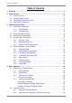
DVR User’s Manual Table of Content 1. Overview .......................................................................................................................7 2. System Setup................................................................................................................8 2.1 Position the Unit...................................................................................................8 2.2 Selecting Video Format..................................................................
DVR User’s Manual 4.3 4.4 4.5 Searching Recorded Video ................................................................................28 4.3.1 Searching by Time................................................................................29 4.3.2 Searching by Event ..............................................................................29 Video Export ......................................................................................................30 4.4.1 ezBurn Introduction ..............
DVR User’s Manual Appendix E: Remote Controller......................................................................................59 Appendix F: Setting up a DVR behind a Router ............................................................
DVR User’s Manual 1. Overview The Proficient MPEG-4 Series DVR is an integrated digital video recorder that combines the features of a time-lapse audio / video recorder, a multiplexer, and a video server to create a single security CCTV solution.
DVR User’s Manual Human Technology: • • • • • ezBurn™ for quick video export ezRecord™ for quick recording setting ezDDNS™ for automatic DDNS configuration IR Remote Control (Optional) Compact Control Keyboard (Optional) Please refer to Appendix B: The Specification Table for more details about features of different models. 2. System Setup The notices and introduction on system installation will be described particularly in this chapter. Please follow the description to operate the unit.
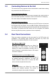
DVR User’s Manual 2.3 Connecting Devices to the Unit This section lists some important notices that should be read before making any connection to the DVR series unit. Connecting Required Devices Before power up the unit, you should connect cameras and a main monitor to the unit for basic operation. If needed, connect a call monitor for displaying full screen video of all installed cameras in sequence.
DVR User’s Manual 4ch model Alarm I/O & RS485 The unit provides an alarm I/O and RS485 port that offers user the flexibility required to connect the unit to the other device. The definitions for pins varies when the DVRs have different channels. Refer to Setup 8ch/16ch models Guide for detailed pin definitions. LAN Connector (RJ-45) The DVR series unit is capable of networking. The LAN port opens the door of the DVR series unit to Ethernet where by the Internet.
DVR User’s Manual 3. General System Setup Before you get started, some general configuration should be setup for the DVR series unit. The following subsections will introduce function keys on the front panel and guide you to setup the configuration of the unit. The regular displayed OSD information and its displayed positions are shown as following figure. The channel title will be displayed on the top-left side of the window, either in full screen mode or in multiple channel mode.
DVR User’s Manual 3.1.2 Function Keys This section describes the functional keys, which are for normal operation, on the front panel of the DVR series unit. Refer to the Setup Guide for the graphical illustration of functional keys. CHANNEL • In both Live and Playback modes, press the CHANNEL key to view the corresponding video in full screen. The number of the CHANNEL keys corresponds to the number of cameras supported by the unit.
DVR User’s Manual If the password protection has not been enabled, press ESC for five seconds to lock/ unlock the functions of these keys. NOTE: Please go to the menu to enable or disable the password protection. ZOOM/ENTER • In OSD menu or selection interface, press this key to make the selection or save settings. • In live full screen view mode, press this key to view a 2× zoom image; press it again to exit zoom mode.
DVR User’s Manual 3.2 Power Up / Down the Unit If you must shut down the DVR series unit for any reason, please use the proper shut down and power up procedures to avoid damaging your DVR unit. To Power Up the Unit Simply plug in the power adapter that came with the package and the DVR will start to boot. The color bar and system checking information will be shown on the monitor and then disappear when the unit has been completely powered up.
DVR User’s Manual The default passwords are shown in the following table. The same passwords are used for entering the remote viewing software DynaRemote Lite. Administrator Password User Password 1234 4321 NOTE: It is strongly suggested to change the passwords to prevent unauthorized access to the unit. After entering the correct password, the Main menu is displayed. Main Menu 1. System Setup 2. Monitor Setup 3. Camera Setup 4. Record Setup 5. Sequence Setup 6. Event Setup 7. Database Setup 8.
DVR User’s Manual 3.4.1 Set Date / Time Set Date / Time Select /
DVR User’s Manual 3.4.2 Daylight Saving Time Daylight Saving Time The item is for those people who live in certain regions to observe Daylight Saving Time. Select to enable, or to disable the function. If the function is disabled, the DST Start / End time and DST Bias will be grayed out and cannot be accessed. NOTE: If this function is enabled, the date/time information will be shown on the screen with a DST icon when playing back recorded video or searching video in the event list.
DVR User’s Manual 3.4.3 Network Time Protocol Setup Time Zone Select
DVR User’s Manual 3.5 Record Schedule / Quality Setting The Record Setup menu allows user to set recording quality, recording schedules, and other recording parameters. Administrator's password is required to access Record Setup menu. In the Main menu, move the cursor to and press ENTER; the following menu is displayed. Record Setup 1. Record Mode 2. Schedule Setup 3. Preset Config 4. Per Camera Config. 5. ezRecord Setup 6. Data Lifetime 7. Circular Recording 8. Purge Data 3.5.
DVR User’s Manual 3.5.2 Preset Record Configuration The is used to select the preset recording quality and frame rate. In normal circumstances, we strongly suggest you set the item to , the default. Below table shows the PPS and picture size under in Half-D1 mode. Please refer to OSD Menu Setup Guide, Section Preset Record Configuration for more detailed information. Halfl-D1 mode (NTSC: 720x240@60PPS; PAL: 720x288@50PPS) 3.5.
DVR User’s Manual 3.5.4 To Record Event Video Only If you want your DVR unit to start recording only when the alarm is triggered, follow the steps: • Enter the OSD setup menu with correct password. • In the OSD setup menu, select menu. Move the cursor to the item , and select . Refer to OSD Menu Setup Guide, Section Preset Record Configuration for more detailed information. 3.5.
DVR User’s Manual 3.5.6 ezRecord Setup This item aims to ease the complicated record settings, and to make the setup much easier. Note that the item can be reached only when you select as the option for . Select from and press ENTER, the sub-menu appears as below figure: ezRecord Setup How Many Days To Record Daytime Record Night Record Weekend Record Record Info Average Normal PPS Average Normal Quality 2 Days Yes Yes Yes 3.
DVR User’s Manual 3.5.7 Circular Recording User can choose to record video in circular mode or in linear mode. If you choose to record in circular mode, then the unit begins to stores new video into the HDD spaces and overwrite the oldest recorded video. If you choose to record in linear mode in stead, the unit stops recording when the HDD is full, and the internal buzzer starts beeping.
DVR User’s Manual 4. Basic Operation The DVR series unit allows user to access some general operations through the front panel easily. The following sections introduce the general operations of the unit. 4.1 Viewing Live / Playback Video The general functions in live and playback mode are described in the following sections. 4.1.1 Viewing Modes The DVR series unit provides user versatile ways of viewing both live and recorded video. Following presents these view formats.
DVR User’s Manual 4.1.2 Digital Zoom Users are able to view a 2× full screen in live mode. To view the 2× full screen, follow the steps. • Press a CHANNEL key to view the corresponding camera in full screen. • Press ZOOM to enter a 2× full screen zoom mode of the selected camera. • If you need to view specific area of the 2× zoomed screen, use Direction keys to pan / tilt the zoomed area around the original image. • Either press ZOOM again or ESC to leave the zoom mode. 4.1.
DVR User’s Manual Key Usage in Playback The key usage is slightly different in playback mode. Following is the key usage found in playback mode. z LEFT (Reverse Playback) The key is used to reverse the recorded video while the unit is playing back. Press the key repeatedly to increase the speed of reverse playback by 1×, 2×, 4×, 8×, 16×, or 32×. z RIGHT (Forward Playback) The key is used to play the recorded video fast forward.
DVR User’s Manual Viewing Live Image in Playback Mode Press the MODE key repeatedly in playback mode, a 16-window viewing mode contains both live and playback image appears. This viewing mode is illustrated as the following figure. The eight windows on the top side of the screen playback the Live video from channel 1 to channel 8 respectively, and the other windows allow user to view Playback image from channel 1 to channel 8. 4.
DVR User’s Manual 4.2.2 Sequence with Call Monitor (8ch and 16ch only) Users are allowed to use the DVR series unit front panel to control a call monitor display without having to access the Main menu. Two viewing modes can be displayed on call monitor: Sequence display and Single camera display. To program the call monitor sequence, see OSD Menu Setup Guide, Section Sequence Setup. Follow the steps to control the call monitor. • Press the CALL key on the front panel to enter call monitor control mode.
DVR User’s Manual 4.3.1 Searching by Time Follow the steps to search video by date and time. • Press SEARCH key to enter the Search menu; the From Time and End Time of the available video is listed on top of the screen. The value is unchangeable. • Use Direction keys to move the cursor for setting the start time; adjusting the date and time values by UP / DOWN keys. • Press ENTER to confirm the settings or ESC to abort.
DVR User’s Manual The list displays events by date, time, triggered camera and alarm type. As some events are deleted, others are displayed. The latest recorded event video will be listed on the top. Follow these steps to search event video through Event List: • Press SEARCH to enter the Search menu. • To search event video that has been recorded on a specific camera, use LEFT / RIGHT to move the cursor and press ENTER to select or de-select a channel.
DVR User’s Manual 4.4.1 ezBurn Introduction Built with the ezBurn technology, ezBurn function provides users the easier way to export desired video with built-in CD/DVD-RW or to an external device, such as an USB ThumbDrive®. TWO keys (SEARCH and COPY) and THREE touches are all you need for completing the export. The entire exporting process will be done through the front panel, without needing to enter the OSD setup menu.
DVR User’s Manual • Press ENTER to start the export; or, press ESC to abort. • If there is no any exportable device connected to the DVR unit, then a warning message will be shown on the screen, as below figure: No exportable device detected. Please install the target device/media to the DVR. Enter: Retry ESC: Exit 4.4.3 To Export Event Video To export event video, follow these steps: • Press SEARCH and play wanted event video. To play event video, refer to Section Searching Recorded Video.
DVR User’s Manual To configure the dome controls settings, see the following sections. 4.5.1 Dome Connection Follow the steps to install dome camera. • See Setup Guide for RS-485 port pin definition. • Connect the R+, R- terminals on the dome camera to the D+, D- terminals on the RS-485 port by RS-485 cable respectively. Refer to the connection figure illustrated in Setup Guide. 4.5.
DVR User’s Manual 4.5.3 RS485 Setup The DVR series unit controls the domes via RS-485 communication protocol. The RS-485 parameters in the DVR series unit must be set to the same parameters set in dome camera. Users are allowed to change the RS-485 settings of the DVR series unit. Select in Main menu, then select from the System Setup menu and press ENTER. The following menu is displayed.
DVR User’s Manual Toggle Hint Screen This function is used to avoid viewing the dome parameter information while controlling dome camera. Press this key to hide the screen. Press it again to redisplay the screen. Iris Open Use to open the Iris on the dome camera. Focus Near Use to focus the dome camera near. Zoom In Use to zoom in the dome camera. This function enables the user to enlarge a certain area. ESC Use to leave dome control mode and return to live and full screen viewing mode.
DVR User’s Manual 4.5.5 Setting Preset Points The DVR series unit allows user to set preset positions. The amount of preset points depends on the dome manufacturer. Follow the steps to set preset points. • Press a Channel key to view the corresponding camera in full screen. • Then press DOME to enter dome control mode. And a Hint Screen shown as below figure displays on the screen. • Press 2 to hide the dome control Hint Screen; press 2 again to toggle the Hint Screen.
DVR User’s Manual 4.5.6 Calling Preset Points Follow the steps to call preset points. • Press a Channel key to view the corresponding camera in full screen. • Then press DOME to enter dome control mode. Then a Hint Screen, shown as blow figure, will display on the screen. • Press 2 to hide the dome control Hint Screen; press 2 again to toggle the Hint Screen. • Press 1 to access the Set/Go Preset function.
DVR User’s Manual 5. Remote Monitoring Software The remote monitoring software is a remote browser-based software application designed to operate with the DVR series products. Using the software, users are allowed to view live and recorded video, and also to configure the DVR series units remotely via a LAN, WAN or Internet on your personal computer.
DVR User’s Manual 5.2 Getting Start of Installation Refer to the following description to install the remote control software. 5.2.1 Changing Internet Settings The PC you want to operate with the remote monitoring software should be set to accept ActiveX plug-ins. Please follow the steps to set the Internet security settings appropriately. • Before operating the remote monitoring software, please check the IP address of your DVR series unit.
DVR User’s Manual • Uncheck “Require server verification (https:) for all sites in this zone”. Type the IP address of the unit in field and click to add this web site to the zone. • Click to confirm the setting and close Trusted sites dialog. • In the Security Level area, click . The Security Settings screen is displayed. • Under , set all items to or . • Click to apply the setting and close the screen.
DVR User’s Manual 5.2.2 Installing Remote Monitoring Software Start the browser to initiate the installation of the remote monitoring software on your personal computer. You can save the IP address of the remote unit as a Favorites item in your web browser to have easy access next time. • Start the IE; you may start it either by clicking on the desktop icon, or by using the Start menu to access it. • Enter the IP address of your DVR series unit in the address bar at the top of the browser.
DVR User’s Manual 5.2.2.1 Log in / Log off You can log in using the or account. account can perform unit configuration freely, while account has more limitation on remote access to the unit. One “Admin” and up to two “User” can access a DVR series unit at the same time. Furthermore, if the “Admin” account is currently accessing the unit’s OSD setup menu via front panel of the unit, then you cannot save information as an “Admin” on the remote monitoring software.
DVR User’s Manual 5.2.2.2 Software Upgrades When a new version of the remote monitoring software is available on your DVR series unit, upgrade will be prompted when you access the unit. Follow the steps to upgrade the software. • The message as the above figure will be prompted. Click to accept version upgrade.
DVR User’s Manual To view the main window in full-screen view, press on your keyboard. The functions on the remote monitoring software will be described in the following sections. 5.3.1 To View Live Video You can view live video from the cameras attached to the DVR series unit by clicking button on the main window toolbar. You can select desired display mode and assign wanted camera view to the window(s) after the live images of the DVR series unit are displayed on the main window.
DVR User’s Manual 5.3.1.2 Operating Cameras with Dome Control The remote monitoring software allows you to control and configure a dome camera remotely. Click on any CAMERA button displayed with a dome icon to view the camera in full screen. The Dome Control Panel (shown as right) will be displayed in the left-bottom side of the main window. The items on the dome control panel are described as follows. Set Preset Points This item is used to set up preset positions.
DVR User’s Manual Zoom You are allowed to zoom-in or zoom-out using the adjusting buttons. Zoom-in to enlarge a certain area and zoom-out to view more area. Direction Buttons These buttons are used to pan and/or tilt the dome camera. Click the arrow button in the direction you want to view. 5.3.2 Instant Recording The Instant Recording function allows you to record video quickly to your PC. NOTE: The Audio function is set to OFF as the default setting. 5.3.2.
DVR User’s Manual 5.3.4 To Playback Video The remote monitoring software allows you to view recorded video either from the DVR series unit, or playback from the hard disk drive of your PC To access the Playback screen, click button on the main window toolbar. There are three tabs in the Playback screen: and tabs. allows you to play back from a DVR series unit.
DVR User’s Manual • You can change the date and time either by typing desired numbers directly or using the arrow buttons. To type directly: Click on day, month and year of date field respectively, and type the desired numbers directly. Follow above steps to adjust the hour, minute and second of time field. To use the arrow buttons: Click on the arrow button next to the date field to display the calendar; then click the left and right arrow at the top of the calendar to change the date.
DVR User’s Manual Follow below steps to play back a downloaded *.drv file with the remote monitoring software. • Click and the file selection screen is displayed. • Select the *.drv video file to playback and click . • Click in the Screen to start the playback, or click to abort. • View the video playback using the Playback controls. • To end the playback, click to return to live video. 5.3.4.
DVR User’s Manual 5.3.5 Search from Event List Click SEARCH, the Event List appears. The List contains information about the alarm events that your unit recorded and saved. Up to 1024 events can be listed in the Event List. The Event List (shown as below figure) displays each event by its number, the date and time of the event, the type of the event (including Alarm In, Motion Detection, Video Loss, and Over Speed), and the camera channel where the event occurred.
DVR User’s Manual 5.3.6 Remote Monitoring Software Trouble Shooting Guide What if the server ask to upgrade the software every time when you try to connect to the DVR series unit unit? If the following screen displays repeatedly, please follow the steps to delete the temporary internet files. • Select from the main menu of the web browser, then , and then click the tab.
DVR User’s Manual Appendix A: Technical Specifications All specifications are subject to change without notice. Specifications 4ch Model 8ch Model 16ch Model BNCx4 / UTPx4, BNCx8 / UTPx8, BNCx16 / UTPx8, 1.0Vp-p, 75 ohm 1.0Vp-p, 75 ohm 1.0Vp-p, 75 ohm Video Input Video Standard NTSC/PAL switch selectable Video Operation Triplex (Live / Playback, Record, and Network) BNCx1, 1.
DVR User’s Manual Storage Up to 2 built-in HDDs Built-in HDD Export USB 2.0 CD / RW (Optional) USB Support USB Thumb Drive Alarm Alarm Input X4, D-Sub 15 pin X8, D-Sub 25 pin N.C./N.O., Programmable Alarm Detection Built-in Buzzer Auditory Alert 16x12 Motion Detection Programmable Video Loss Detection Alarm Relay Output X16, D-Sub 25 pin X1, D-Sub 15 pin X1, D-Sub 25 pin X1, D-Sub 25 pin 3.0 A / 30 VDC or 3.
DVR User’s Manual Appendix B: The Specification Table Below table lists the different features among models. Features Proficient MPEG-4 DVR Series 16ch 8ch 4ch 120 120 120 * Compression Method M M M IP Camera Compatibility - - - Per Channel Configuration ▓ ▓ ▓ Max.
DVR User’s Manual Appendix C: Connect UTP Camera UTP, short for Unshielded Twisted Pair, is a popular type of cables that is one of the most common medium in telecommunication industry. Installing the UTP module allows your DVR to supply power to and transmit images from any four distinctive UTP cameras through the UTP cables (CAT5). This leads to an economical and fast installation of surveillance.
DVR User’s Manual Follow the same procedure if you will be installing more UTP Cameras to CH2, CH3, or CH4. NOTE: Do NOT insert both BNC and UTP video sources to the same channel simultaneously, or the video will not function correctly and it may cause the video to look like the figure below. For instance, if you have already installed a UTP Camera to channel 1, do not install another camera to the BNC port of channel 1.
DVR User’s Manual Appendix D: Connect Analog Camera via UTP Converter Introduction: The UTP converter is made especially for users who want to build a connection between an UTP DVR and a traditional analog camera, which allows the transmission of power and video signal through one CAT5 cable. The UTP converter has two cables at one end—one cable for connecting with the camera’s BNC video connector; and the other for connecting with power jack of the camera.
DVR User’s Manual Appendix C: Recommended HDDs The followings are lists of recommended HDDs. Refer to PATA HDD list if the DVR is PATA compatible, or else refer to SATA HDD list if the DVR is SATA compatible. PATA HDD: Brand Seagate Western Digital HITACHI Model Name SV35 Series™ DB35 Series™ Barracuda® 7200.9 Barracuda® 7200.9 Barracuda® 7200.10 Barracuda® 7200.
DVR User’s Manual Appendix E: Remote Controller A remote control is provided for the DVR unit.
DVR User’s Manual The keys of the remote control function as the keys of the front panel of the DVR. The only difference between the remote control and the front panel keys is the “DVR SEL” key. The DVR Selection key is used to switch control between each DVR. The remote control can be used to control up to 16 DVRs. To setup the remote control, the first thing you need to do is to assign a unique DVR Unit ID to each DVR.
DVR User’s Manual Appendix F: Setting up a DVR behind a Router This appendix describes how to set up a router if the DVR connects to the internet via a router. To properly operate a web server, e.g. a DVR, the user has to set up both the IP and port of the DVR, which are essential for data and command transmission. The port setting is adjustable in OSD setup menu of the DVR and only one port is needed to do remote operation.
DVR User’s Manual Following is an example of how the router should be set. Router (D-Link DI-724P+) WAN IP: 218.160.54.13 LAN IP: 192.168.0.1 PC IP: 192.168.0.100 DVR 1 IP: 192.168.0.167 Trigger port: 80 DVR 2 IP: 192.168.0.200 Trigger port: 81 • To change the setting of the router, you need a PC with web browser. • Connect to D-Link DI-724P+ from PC via IE. The setup screen will be shown after entering the correct username and password.
DVR User’s Manual A. Select to set up the service. B. Enter the name of the setting in the Name field: DVR 1. C. Enter Private IP: 167 D. Choose as the Protocol Type. E. Enter Private Port: 80. F. Enter Public Port: 80. G. Click for the Schedule setting. H. Click . • Click to go on when the following screen displays. • Follow the steps to set up web port forward to DVR 2. A. Click to set up the service. B.