XM4400 Adhesive Application & Laminating System User’s Guide P/N 3355 Revision: C 02/09/10 1
Table of Contents Introduction……………………………………………………………………………………… 3 Technical Specifications………………………………………………………………………. 3 Warnings………………………………………………………………………………………… 3 Contents of the XM4400 machine box……………….……………………………………… 4 Unpacking and assembling the cart…………………………………………………………. 4 Unpacking and positioning the machine…………………………………………………….
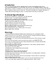
Introduction Thank you for purchasing the XyronPro XM4400 Adhesive Transfer and Laminating System. We are sure you will find this laminator to be useful, reliable, and easy-to-use. The XM4400 is designed to apply high quality, adhesive or bubble free laminate to posters, banners, and any other visuals up to 42 inches wide and up to 300 feet long that you want to protect for future use.
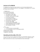
Contents of the XM4400 The XM4400 is fully assembled and requires minimal set up other than unpacking the machine, assembly of the cart, mounting the machine to the cart, plugging it in, and loading the film. You will find the contents of the box to include: 1. XM4400 machine 2. In-Feed tray with paddle [3309] 3. Un-assembled cart components a. (2) Rectangle Cross Bar [3346] b. (2) Cart frame end pieces [3806] c. (4) 1/4"-20" x 2.25" hex head bolts [3330] d. (4) 1/4" washers [2143-02] e.
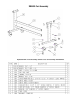
XM4400 Cart Assembly Exploded view of Cart Assembly: Shows Cross bar assembly and hardware 5
Cart Assembly Instructions 1. The cart assembly is begun by assembly of the right side assembly frame end to the 2 cross bars [3346] with a 2 ¼” Hex Head bolt [3330] with washer [2143-02] and split lock washer [2189-04]. Install the upper cross bar by Inserting the metal dowel pin into the pilot hole and then inserting and locating the threaded bolt into the screw hole. Tighten the bolt using the 3/16” Hex wrench for assembly [3352] and then assemble the bottom cross bar. See figure 1 / 2.
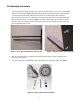
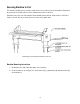
4. To assemble the caster wheel frame, begin by mounting the caster frames to the cart frame ends by threading the cart threaded stem into bottom weld nut of the cart frame ends. See figure 4 / 5. Figure 4/5: Using hardware supplied, secure caster frame to cart 5. Thread the caster bolt stem up through the weld nut on the bottom side and through hole on the top side of the new cart frame ends. Secure using a Black Washer and Black Nylock nut.
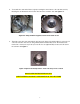
6. Next assemble the casters by inserting the wheel into the caster frames and secure with the caster bold and nut which were provided with the casters. See figure 7 / 8 Figure 7 / 8: Caster wheel assembled 7. Next assemble the casters by inserting the wheel into the caster frames and secure with the caster bold and nut which were provided with the casters.
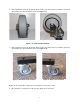
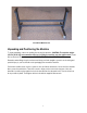
Assembled Machine Cart Unpacking and Positioning the Machine To begin unpacking, remove the packing from around the machine. CAUTION: The machine weighs 155 Lbs [70.45 Kg], have someone assist you in lifting the machine onto the mobile stand. Please lift from under the ends of the machine. DO NOT LIFT USING ANY OF THE ROLLERS. Remember when lifting to bend your knees and keep your back straight to prevent over stressing and possible injury to your back. Remove the packaging from around the machine.
Securing Machine to Cart The machine should be placed so that you have full access to all four sides of the machine. Ensure that the power and foot pedal cables are not in a hazardous position on the floor. Check the area to the rear of the machine where laminated items will exit. A flat surface is desired for items to exit onto. Be sure to clean the area so items do not gather dust. Positioning and securing the machine on the cart Machine Mounting Instructions 1.
XM4400 Control Panel Control panel – Top View Control panel - Front View The control panel for the XM4400 is located on the right hand side of the machine. The following paragraphs review each of the controls. Auto / Foot The Auto/Foot Switch changes the motor control modes. Auto mode allows the motor to run constantly. Foot mode allows you to start and stop the machine by pressing and releasing the foot pedal, allowing for greater control. Foot mode is the default.
Film Pre-Cautions Below are several precautions which must be followed when handling film: 1. Adhesive side of the film must be oriented away (on the outside) from the laminating roll. Otherwise it will immediately bond to the roll, creating a major clean-up project. 2. Films have a shiny side and a dull side. The dull side is the one with the adhesive. The dull side should ALWAYS face outward from the laminating roll. 3.
Machine Rollers, Idler Bars and Supply Roll Locations Web Path Diagram for Loading Laminate Laminate Roll Mask Roll Laminate Path Adhesive Path Laminate Roll 13 Adhesive Roll
Loading Film Each roll of material comes with an extra 5 feet of material that allows for proper loading without wasting the purchased material. Before starting the loading process, remove tray from the machine. Step 1: • • • Match the colored dots on the end of each supply roll with the corresponding dots on the side of the machine. Note which roll is identified as "top" and "bottom." The "bottom" roll has a starter section.
Loading Film (Continued) Step 3: • • Make certain the lower film is tight. If necessary, rotate the supply roll backwards to tighten. Grasp the film from the upper supply roll, and adhere it to the exposed adhesive on the lower supply roll. For best results, adhere the top film 1 inch below the round steel idler bar. By carefully aligning the edges, keeping the film tight and avoiding wrinkles, film waste will be minimized. Step 4: • • • • • • Use the foot pedal to run the film through the machine.
Troubleshooting Tips for Loading Film If material wraps around the top pinch roller: 1. Remove the bar located on the output side of the pinch rollers by lifting it out of the way. 3. Be careful not to damage the rubber rollers, feed some more material through the system. 4. Run enough material through the system to eliminate all wrinkles. 5. Remove the excess material.
Feeding Items into Machine The initial feeding of an item into the machine is the most important part of the process. If an item enters the machine on an angle, or with wrinkles in the leading edge, the output may end up with wrinkles. Some items are easier than others. Generally smaller and more rigid items are the easiest. A very large, thin item is more challenging, but should provide few problems if fed into the machine correctly.
Cutting Material To cut the material off after your document(s) have passed through the machine, please follow the instructions below: 1. Place the document over the edge of the output side of the machine housing. 2. Using the handheld cutter [3351], place the cutter onto the edge of the material at the point you wish to cut off the excess. 3. Pull material tight to apply tension to film when cutting 4. To cut the material, pull the blade along the edge of the machine to cut the material. 5.
Feeding multiple items You can feed as many small items into the machine next to one another as you are capable of handling, however, all items for side-by-side laminating must be the same thickness. If you are feeding items with a combined width narrower than that of the film and of the same thickness, you can feed them side-by-side to prevent wasting material.
Machine Troubleshooting SYMPTOM Long documents are not aligned with film layers after laminating. POSSIBLE PROBLEM Feed tray not installed correctly. Documents tend to wrinkle during lamination. Verify tray is completely installed. Verify supply rolls are completely seated at base of grooves in side plate. Clean adhesive buildup from blade using isopropyl alcohol. Replace blade if necessary. Handheld Cutter does not cut well. Film does not exit machine under pivoting cutter assembly.
Machine Troubleshooting (Continued) SYMPTOM Film does not lay flat, curls and / or wrinkles. The machine will not run. POSSIBLE PROBLEM Initial loading of film without advancement through machine until advancement could cause adhesive buildup on lower idler bar. Tension on film may cause wrinkles and is not a film quality issue. Loss of power or mechanical stop has been released. TEST/ACTION Clean adhesive buildup from idler roller using isopropyl alcohol.
XM4400 MACHINE EXPLODED VIEW MAINTENANCE SCHEDULE Monthly • • • • • Every Six Months • • Daily Clean the rolls Inspect the electrical cord for damage Inspect the optional footswitch for damage Check the chain tension Inspect the area around the laminator for possible hazards [i.e. dust buildup, combustible items, objects on floor, etc…] Lubricate the grease fittings and chain Check wire termination tightness SUPPLY ROLLS FOR XM4400 Product No.
MACHINE CLEANING POINTS CLEANING INSTRUCTIONS 1. Clean only when needed, with recommended cleaning solution. Isopropyl alcohol is recommended. 2. Be careful with knives near the rollers. Cutting a roller will cause repeating marks in the rollers, and is non warranty damage. 3. Do not allow very thick objects to pass through the rollers. A large irregular object passing through the rollers may cause damage. Use the minimum amount of pressure necessary to clean the rolls.
REPLACING SUPPLY ROLLS 1 - Insert New Rolls Before starting this process make sure the power switch is in the off position, the auto/foot switch is set to foot and the directional switch set to forward. Locate the colored dots on the supply roll ends. Each roll will be designated as top or bottom. Matching colored dots, place rolls into machine. The bottom roll will have a laminated starter ready for use.
CONTACTING TECHNICAL SUPPORT For machine parts and technical service in North America, please call: 1-800-793-3523. Please provide serial number when calling for service. In Europe, please call: +49 711 8103 0. PRODUCT WARRANTY Xyron, Inc. warrants that the Xyron XM4400 is free from defects in material and workmanship for a period of one (1) year from the date of purchase. Xyron, Inc.