*3 6HULHV ,QVWDOODWLRQ *XLGH *3 ३জش६ ඞହછ
NOTE: This Installation Guide describes GP4000 Series except GP-4100 Series, GP4201TM and GP-4301TM. Overview Package Contents..........................................................................................4 About the Manual...........................................................................................5 Global Code ...................................................................................................5 Electrical Specifications 1. GP-4200/4300/4400 Series ................
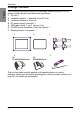
Overview English Package Contents The following items are included in the package.
Overview About the Manual Manual Contents GP4000 Series Hardware Manual Specifications, dimensions, accessories, system design, standards, and other details. English This manual describes wiring and installation procedures. For more detailed information, refer to the manuals indicated below. Device/PLC System configuration of connected devices (PLCs and Connection Manual other devices), communication settings examples, connection wiring diagram, and other details.
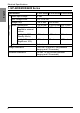
Electrical Specifications Specification Power Supply English 1. GP-4200/4300/4400 Series GP-4200 Series GP-4300 Series GP-4400 Series Rated Input Voltage 24 Vdc Input Voltage Limits 19.2...28.8 Vdc Voltage Drop 2 ms or less Power Consumption 9.6W or less 10.5W or less 12W or less 5 ms or less When power is not supplied to external devices 5.2W or less 6.5W or less 8W or less Backlight is OFF (Standby Mode) 4.2W or less 4.5W or less 5W or less Backlight Dimmed (Brightness: 20%) 4.
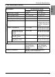
Electrical Specifications Specification GP-4500/4600 Series DC Model AC Model 24 Vdc 100...240 Vac Input Voltage Limits 19.2...28.8 Vdc 85...264 Vac Rated Frequency - 50/60 Hz Rated Frequency Range - 47...
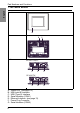
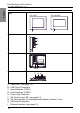
Part Numbers and Functions English 1. GP-4200 Series Front A Rear B Bottom C GP-4201T/4203T F E D G D GP-4201TW F A: B: C: D: E: F: G: 8 Status LED (see page.13) USB (mini-B) Interface USB (Type A) Interface Serial Interface (COM1) Ethernet Interface (see page.
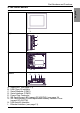
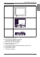
Part Numbers and Functions English 2. GP-4300 Series Front A Right B C D Rear E Bottom E F G H I A: B: C: D: E: F: G: Status LED (see page. 13) USB (Type A) Interface Serial Interface (COM1) Serial Interface (COM2) Power Plug Connector SD Card Access LED (except GP-4301TW) (see page.13) SD Card Interface Cover/Replacement Battery Insertion Cover (except GP-4301TW) H: USB (mini-B) Interface I: Ethernet Interface (see page.
Part Numbers and Functions English 3. GP-4400 Series Front GP-4401T GP-4401WW A A Right B C D Rear E F Bottom E A: B: C: D: E: F: G: H: I: 10 G HI Status LED (see page.13) USB (Type A) Interface Serial Interface (COM1) Serial Interface (COM2) Power Plug Connector SD Card Access LED (see page.13) SD Card Interface Cover/Replacement Battery Insertion Cover USB (mini-B) Interface Ethernet Interface (see page.
Part Numbers and Functions English 4. GP-4500 Series Front A Rear B C Bottom I H B F E G D A: Status LED (see page.13) B: Power Input Terminal Block (AC model), Power Plug Connector (DC model) C: SD Card Access LED (see page.13) D: Ethernet Interface (see page.
Part Numbers and Functions English 5. GP-4600 Series Front A Rear B C Bottom I H B F E G D A: Status LED (see page.13) B: Power Input Terminal Block (AC model), Power Plug Connector (DC model) C: SD Card Access LED (see page.13) D: Ethernet Interface (see page.
Part Numbers and Functions (1) Status LED Color Indicator Operation Mode (Drawing) Green ON Offline - In operation Flashing Orange Red RUN In operation Flashing Logic execution mode (when logic is enabled) STOP Software starting up ON Power is turned ON. Flashing In operation LED fade (Green) ON The GP unit’s “Backlight Control” is set to Standby Mode and the screen has gone blank. Major Error – OFF Power is turned OFF.
Interface English Serial Interface Note: For instructions on how to connect to other devices, always refer to the “GP-Pro EX Device/PLC Connection Manual”. DANGER ELECTRIC SHOCK The serial port is not isolated. The SG (signal ground) and the FG (frame ground) terminals are connected inside the unit. When using the SG terminal to connect an external device to the unit: • Verify that a short-circuit loop is not created when you set up the system.
Interface 1. Connection for Serial Interface COM1 GP-4201T RS-232C or RS-422/RS-485 (see page.16, 17) English Pin assign of each serial interface is explained in reference page. COM2 - GP-4201TW RS-232C (see page.16) GP-4203T RS-485 (isolation) (see page.18) RS-422/RS-485 (see page.17) GP-4301T RS-232C (see page.16) RS-422/RS-485 (see page.17) GP-4301TW RS-232C (see page.16) RS-422/RS-485 (see page.17) GP-4303T RS-232C (see page.16) RS-485 (isolation) (see page.
Interface English 2. RS-232C D-Sub 9 pin plug connector via an RS-232C cable. Pin Number RS-232C Signal Name Direction Meaning 1 CD Input Carrier Detect 2 RD(RXD) Input Receive Data 3 SD(TXD) Output Send Data 4 ER(DTR) Output Data Terminal Ready 5 SG – Signal Ground 6 DR(DSR) Input Data Set Ready 7 RS(RTS) Output Request to Send 8 CS(CTS) Input Send Possible 9 CI(RI)/VCC Input/– Called Status Display +5V±5% Output 0.
Interface 3. RS-422/485 Pin Number English D-Sub 9 pin plug connector via an RS-422/485 cable.
Interface English 4. RS-485 (isolation) D-Sub 9 pin socket connector via an RS-485/PROFIBUS/MPI cable.
Installation • • • • Decide on the thickness of the enclosure wall, based on the level of strength required: 1.6 mm (0.06 in.) to 5 mm (0.2 in.). Even if panel thickness is within recommend range for “Panel Cut Dimensions”, the panel could warp, depending on panel’s material, size, and installation location of GP unit or other devices. To prevent panel warpage, the installation surface may need to be strengthened.
Installation When installing the GP unit in a slanted position with an incline more than 30°, the ambient temperature must not exceed 40 °C (104 °F). You may need to use forced air cooling (fan, A/C) to ensure the ambient operating temperature is 40°C or less (104 °F or less). For easier maintenance, operation and improved ventilation, install the GP unit at least 100 mm (3.94 in.) away from adjacent structures and other equipment as shown in the following illustration. • 100 3.94 • 100 3.94 100 3.
Installation Create a Panel Cut and insert the GP into the panel from the front. R C English A B 3 GP-4200 Series A B 118.5 +1 mm 92.5 +1 mm +0.04 (4.67 -0 +0.04 (3.64 -0 -0 -0 in.) 156 +1 mm 123.5 +1 mm +0.04 (6.14 -0 +0.04 (4.86 -0 -0 in.) 159.5 +1 mm -0 +0.04 (8.05 -0 +0.04 (6.28 -0 GP-4500 Series A 259 +1 mm GP-4501T GP-4503T -0 +0.04 (10.2 -0 GP-4501TW 301.5 +1 -0 +0.04 -0 +0.04 (11.87 -0 3 mm (0.12 in.) maximum C R in.) B C 201 +1 mm 1.6...5 mm 3 mm (0.12 in.
Installation English 4 Insert the installation fasteners into the GP unit’s insertion slots on the top and bottom sides. (left and right sides for the GP-4200 Series.) If the fasteners are not correctly attached, the GP unit may shift or fall out. Installation Panel Hook Slots Slots (GP-4201T) 22 (GP-4301T) 5 Slide the fasteners to the back. 6 Use a Phillips screwdriver to tighten each fastener screw and secure the GP unit in place. The necessary torque is 0.5 Nm (4.4 lb-in).
Installation English NOTICE BROKEN ENCLOSURE • Do not exert more than 0.5 Nm (4.4 in-lb) of torque when tightening the fastener’s screws. • For use on a flat surface of a Type 1, Type 4X (Indoor Use Only) or Type 13 Enclosure Failure to follow these instructions can result in equipment damage.
Installation English 3. Removal Procedures Step Action 1 Loosen the installation fasteners (4) from the GP unit. 2 Remove the GP unit slowly from the panel while pressing the projections on the top of the GP unit. (1) (1) (1) projections Note : • You could damage the GP unit if you try and remove it without holding down the projections. • Watch your fingers so they do not get caught when holding down the projections.
Wiring English Wiring WARNING HAZARD OF ELECTRIC SHOCK, EXPLOSION OR ARC FLASH • Remove all power from the device before removing any elements of the system, and prior to installing or removing any accessories, hardware, or cables. • Remove power before wiring the GP unit’s power terminals. • The DC model uses only 24 Vdc power. Using any other level of power can damage both the power supply and the GP unit. • The AC model is designed to use 100 Vac to 240 Vac input.
Wiring English 1. Connecting the AC Power Cord Field wiring terminal marking for wire type (75°C (167 °F) Copper conductors only) AC Power Cord Grounding Wire Power Cord Double-insulated Wire 0.75 to 3.5 mm2 (18-12AWG) 0.75 to 3.5 mm2 (18-12AWG) Recommended Ring Terminal*1 J.S.T Mfg. Co., Ltd Compatible: V1.25-M4 (18-16AWG) V2-P4 (16-14AWG) V5.5-S4 (14-12AWG) J.S.T Mfg. Co., Ltd Compatible: V1.25-M4 (18-16AWG) V2-P4 (16-14AWG) V5.5-S4 (14-12AWG) (1) φ4.3 mm (0.17 in.) or more (1) φ4.
Wiring Remove screws from the L, N, and FG (functional ground) terminals. Attach the ring terminals and reinsert the screws. Check each wire to make sure the connections are correct. English 3 Note : • Terminal Block: 1.4 N•m (12.4 lb•in.) • FG (functional ground) Terminal: 1.4 N•m (12.4 lb•in.) )* 4 Close the terminal strip’s clear plastic cover. 2. Connecting the DC Power Cord Field wiring terminal marking for wire type (75°C (167 °F) Copper conductors only) Power Cord Diameter 0.75 to 2.
English Wiring Power Connector Specifications: Spring Clamp Terminal Blocks GP-4200 Series / GP-4300 Series / GP-4400 Series GP-4500 Series / GP-4600 Series FG + FG + Connection Wire + 24 Vdc – 0 Vdc FG Grounded terminal connected to the panel chassis. Note: The DC power supply connector (plug) for GP-4200/4300/4400 Series is PFXZCBCNDC1 (manufactured by Pro-face). The DC power supply connector (plug) for GP-4500 Series / GP-4600 Series is PFXZCBCNDC2 (manufactured by Pro-face).
Wiring How to connect the DC Power Cord Action 1 Confirm the power cord is not connected to the power supply. 2 Check the rated voltage, and remove the “DC24V” sticker on the DC power supply connector. 3 Remove 10 mm (0.39 in.) of the vinyl membrane off the ends of the power cord wires. mm in. English Step 10 0.39 4 If using stranded wire, twist the ends. Tinning the ends with solder reduces risk of fraying and ensures good electrical transfer.
Wiring English 3. Wiring Cautions Improving Noise/Surge Resistance • The GP unit’s power supply cord should not be bundled with or kept close to main circuit lines (high voltage, high current), power lines, or input/ output lines, and their various systems should be kept separate. When power lines cannot be wired via a separate system, use shielded cables for input/output lines. • Make the power cord as short as possible, and be sure to twist the ends of the wires together (i.e.
USB Cable Clamp When using a USB device, attach a USB cable clamp to the USB interface to prevent the USB cable from being disconnected. WARNING RECOMMENDATION FOR RESTRICTED AREAS • Verify the power, input, and output (I/O) wiring are in accordance with Class I, Division 2 wiring methods. • Substitution of any component may impair suitability for Class I, Division 2. • Confirm that the USB cable has been fixed with the USB cable clamp before using the USB interface.
USB Cable Clamp English 3 As shown, pass the tie through the clip hole. Next, turn the tie and pass it through the head so that the USB cable can pass through the center of the tie loop. The clip is now attached to the USB cable. Note: • • 4 Check the direction of the head beforehand. Make sure the USB cable is through the center of the tie loop and that the tie can pass through the head.
Standards Names GP-4200 Series GP-4300 Series GP-4400 Series GP-4500 Series English Relevant Standards Registration Model No.
English Standards The GP unit is manufactured in accordance with: • Standard UL 508 and CSA C22.2 n°142 for Industrial Control Equipment • Standard ANSI/ISA - 12.12.01 and CSA C22.2 n°213 for Electrical Equipment for Use in Class I, Division 2 Hazardous Locations Note: • • • • For use in Pollution Degree 2 environments. For use on a flat surface of a Type 1, Type 4X (Indoor Use Only) or Type 13 Enclosure. 24V DC input unit must be used with a Class 2 power supply.
Standards English CAUTION ENVIRONMENTAL HAZARDS TO THE EQUIPMENT • Allow the device to reach the surrounding air temperature, not exceeding the following values, before turning the device on: 50°C (122°F): GP-4200 Series, GP-4301TW, GP-4401WW, and GP-4501TW DC models. 55°C (131°F): GP-4301T, GP-4303T, GP-4401T, GP-4501T/4503T DC models, GP4500 Series AC models, and GP-4600 Series. • Do not turn on the device if condensation has occurred inside the device.
36 English
铅 (Pb) 汞 (Hg) 镉 (Cd) 六价铬 (Cr6+) 有毒有害物质或元素 多溴联苯 (PBB) 多溴二苯醚 (PBDE) 15 显示器 × ○ ○ ○ ○ ○ 印刷线路板 × ○ ○ ○ ○ ○ 机箱、底盘 ○ ○ ○ ○ ○ ○ ○:表示所有该产品的均质材料中,其有毒有害物质的含量低于 SJ/T11363-2006 标准所规定的最低要求。 ×:表示至少一种该产品的均质材料中,其有毒有害物质的含量高于 SJ/T11363-2006 标准所规定的最低限度。 部件名称 带显示功能 主体产品 中国 RoHS 相关资料 (本资料是中国 RoHS 的必备资料。) (この情報は、中国 RoHS に対して必要な情報です。) (This information is essential for China RoHS.