
User guide

Specifications
54
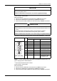
Interfit bracket is #4-40 (UNC).
Recommendations:
z Cable Connector: XM2D-0901 manufactured by OMRON Corporation.
z Cable Cover: XM2S-0913 manufactured by OMRON Corporation.
z Jack Screw (#4-40 UNC): XM2Z-0073 manufactured by OMRON Corporation.
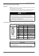
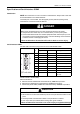
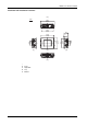
GP-4201TW: D-Sub 9 pin plug connector via an RS-232C cable.
NOTE:
*1
You can switch pin #9 between RI and VCC via software.
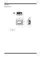
Pin Connection Pin
No.
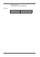
RS-422/RS-485
Signal Name Direction Meaning
1 RDA Input Receive Data A (+)
2 RDB Input Receive Data B (-)
3 SDA Output Send Data A (+)
4 ERA Output Data Terminal Ready A (+)
5 SG - Signal Ground
6 CSB Input Send Possible B (-)
7 SDB Output Send Data B (-)
8 CSA Input Send Possible A (+)
9 ERB Output Data Terminal Ready B (-)
Shell FG – Frame Ground (Common
with SG)
CAUTION
LOSS OF COMMUNICATION
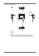
z All connections to the communication ports must not put excessive stress on the
ports.
z Securely attach communication cables to the panel wall or cabinet.
z Use only D-Sub 9 pin cables with a locking tab in good condition.
Failure to follow these instructions can result in injury or equipment damage.
Pin Connection Pin
No.
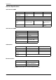
RS-232C
Signal Name Direction Meaning
1 CD Input Carrier Detect
2 RD(RXD) Input Receive Data
3 SD(TXD) Output Send Data
4 ER(DTR) Output Data Terminal Ready
5 SG - Signal Ground
6 DR(DSR) Input Data Set Ready
7 RS(RTS) Output Request to Send
8 CS(CTS) Input Send possible
9 CI(RI)/VCC Input/– Called Status Display
+5V±5% Output 0.25A
*1
Shell FG – Frame Ground (Common
with SG)
9
6
5
1
(GP unit side)
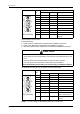
9
6
5
1
(GP unit side)