
User guide

Parts/Functions
36
*1
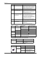
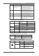
Status LED operations are as shown below:
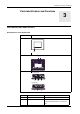
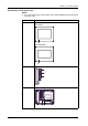
Bottom
Part Name Description
A Status LED
*1
B USB (Type A) Interface Conforms to USB2.0 (Type A) x 1. Power
supply voltage: 5Vdc+/-5%. Output Current:
500 mA or less. Maximum communication
distance: 5 m (16.4 ft).
C Serial Interface (COM1) RS-232C Serial Interface. Connector: D-Sub 9
pin (plug) x 1.
D Serial Interface (COM2) RS-422/485 Serial Interface. Connector: D-
Sub 9 pin (plug) x 1.
E Power Plug Connector -
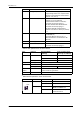
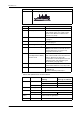
F
SD Card Access LED
*2
This lamp lights up when SD Card is inserted.
NOTE: Do not remove or insert the SD Card
when the LED lamp is on. Doing so may
damage data on the SD Card.
G SD Card Interface
Cover/Replacement Battery
Insertion Cover
For information on how to open the cover, and
insert or remove the SD Card, refer to SD Card
Insertion / Removal (see page 150).
For information on how to open the cover and
replace the battery, refer to Replacing the
Primary Battery (see page 168).
H USB (mini-B) Interface Conforms to USB2.0 (mini-B) x 1.
Communication Distance: 5 m (16.4 ft) or less.
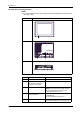
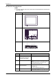
I
Ethernet Interface
*3
Ethernet transmission interface (10BASE-
T/100BASE-TX)
Connector: Modular jack (RJ-45) x 1.
Color Indicator Operation Mode
(Drawing)
Logic execution mode
(when logic is enabled)
Green ON Offline –
In operation RUN
Flashing In operation STOP
Orange Flashing Software starting up.
Red ON Power is turned ON.
Flashing In operation Major Error
LED fade
(Green)
ON The GP unit’s "Backlight Control" is set to Standby Mode
and the screen has gone blank.
- OFF Power is turned OFF.
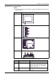
Side GP-4400 Series
EGH I