
User guide

GP4000 Series Hardware Manual
181
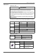
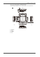
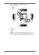
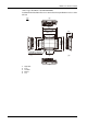
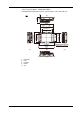
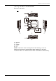
LED Indications
(1)Maintenance LED
*1 For details on the Standby Mode function and on the operations to use in the
system data area to turn the screen off, read the "GP-Pro EX Reference Manual".
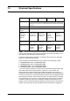
(2)SD Card Access LED
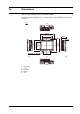
(3)Ethernet LED
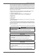
WARNING
UNINTENDED EQUIPMENT OPERATION
You cannot check the maintenance LED from the front of the GP unit.
z Design software by considering the possibility that touch operations may be
performed while an error has occurred.
z To prevent malfunctions caused by touch operations, design software so that
switches and other controls arranged on the screen do not function when you
want the screen to be off even if these controls are accessed with touch
operations.
*1
Failure to follow these instructions can result in death, serious injury, or
equipment damage.
Color Indicator Operation Mode
(Drawing)
Logic execution mode
(when logic is enabled)
Green ON Offline –
In operation RUN
Flashing In operation STOP
Orange Flashing Software starting up.
Red ON Power is turned ON.
Flashing In operation Major Error
LED fade
(Green)
ON The GP unit’s "Backlight Control" is set to Standby Mode
and the screen has gone blank.
- OFF Power is turned OFF.
Color Indicator Description
Green (Active) ON The SD Card is inserted.
OFF The SD Card is not inserted or is not
being accessed.
Color Indicator Description
Green (Active) Flashing Data transmission is occurring.
OFF No data transmission.
Green (Link) ON Data transmission is available in
10BASE-T/100BASE-TX.
OFF No connection or subsequent
transmission failure.
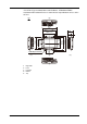
Link
Active