
User guide

GP4000 Series Hardware Manual
179
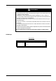
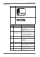
PFXGP4501TADR
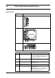
Side PFXGP4501TADR
Rear
Bottom
Part Name Description
A Power Plug Connector -
B SD Card Access LED This lamp lights up when SD Card is inserted.
( see page 181)
NOTE: Do not remove or insert the SD Card
when the LED lamp is on. Doing so may
damage data on the SD Card.
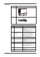
C SD Card Interface
Cover/Replacement Battery
Insertion Cover
For information on how to open the cover, and
insert or remove the SD Card, refer to SD Card
Insertion/Removal (see page 150).
For information on how to open the cover and
replace the battery, refer to Replacing the
Primary Battery (see page 168).
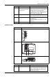
D USB (mini-B) Interface Conforms to USB2.0 (mini-B) x 1.
Communication Distance: 5 m (16.4 ft) or less.
E Ethernet Interface Ethernet transmission interface (10BASE-
T/100BASE-TX)
Connector: Modular jack (RJ-45) x 1. ( see
page 181)
F Maintenance LED ( see page 181)
G USB (Type A) Interface Conforms to USB2.0 (Type A) x 1. Power
supply voltage: 5Vdc+/-5%. Output Current:
500 mA or less. Maximum communication
distance: 5 m (16.4 ft).
H Serial Interface (COM1) RS-232C Serial Interface.
Connector: D-Sub 9 pin (plug) x 1.
I Serial Interface (COM2) RS-422/485 Serial Interface. Connector: D-
Sub 9 pin (plug) x 1.
$%
)&'(
*
+
,