
User guide

GP4000 Series Hardware Manual
127
Specifications of Serial Interface COM2
Introduction
NOTE: For instructions on how to connect to other devices, always refer to the “GP-
Pro EX Device/PLC Connection Manual”.
The COM2 port of GP-4601T is not isolated. The SG (signal ground) and FG (frame
ground) terminals are connected inside the GP unit.
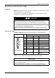
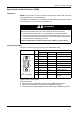
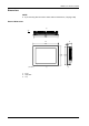
Serial Interface COM2
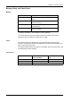
GP-4601T: D-Sub 9 pin plug connector via an RS-422/485 cable.
Interfit bracket is #4-40 (UNC).
Recommendations:
z Cable Connector: XM2D-0901 manufactured by OMRON Corporation.
z Cable Cover: XM2S-0913 manufactured by OMRON Corporation.
z Jack Screw (#4-40 UNC): XM2Z-0073 manufactured by OMRON Corporation.
DANGER
ELECTRIC SHOCK
When using the SG terminal to connect an external device to the panel:
z Verify that a short-circuit loop is not created when you set up the system.
z Connect the #5 SG terminal to remote equipment when the host (PLC) unit is
not isolated. Connect the #5 SG terminal to a known reliable ground connection
to reduce the risk of damaging the circuit.
Failure to follow these instructions will result in death or serious injury.
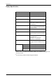
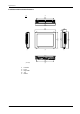
Pin Connection Pin
No.
RS-422/RS-485
Signal Name Direction Meaning
1 RDA Input Receive Data A (+)
2 RDB Input Receive Data B (-)
3 SDA Output Send Data A (+)
4 ERA Output Data Terminal Ready A (+)
5 SG - Signal Ground
6 CSB Input Send Possible B (-)
7 SDB Output Send Data B (-)
8 CSA Input Send Possible A (+)
9 ERB Output Data Terminal Ready B (-)
Shell FG – Frame Ground (Common
with SG)
9
6
5
1
(GP unit side)