
User guide

6
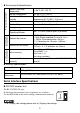
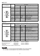
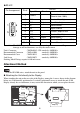
RS-422
Unit's Connector : XM3B-0942-132L<made by OMRON>
Recommended Connector : XM2A-0901 <made by OMRON>
Recommended Cover : XM2S-0913 <made by OMRON>
Jack Screw : XM2Z-0073 <made by OMRON>
Stacking Metal Fittings require #4-40 inch screw.
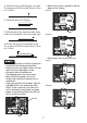
Attachment Method
• For the GP-4200 series, attach the unit to the panel.
Attaching the Unit directly to the Display
When attaching the unit on the rear side of the Display, among the 4 screws shown in the diagram
below, use 2 horizontally positioned or 2 vertically positioned screws to attach the unit. If the
Display already has an attachment, it may restrict the direction in which you can place the unit.
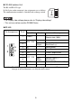
Pin Arrangement Pin #
RS-422
Signal Name Direction Meaning
1TRMRX -
Termination
(Receive side: 100Ω)
2 RDA Input Receive Data A(+)
3 SDA Output Send Data A (+)
4 NC - No connection
5 SG - Signal Ground
6VCC -
+5V
±5% output 0.05A
*1
*1 The VCC output for Pin #6 is not protected against overcurrent. To prevent
damage or unit malfunctions, use only the rated current.
7 RDB Input Receive Data B(-)
8 SDB Output Send Data B(-)
9 TRMTX - Termination (Send side: 100Ω)
Shell FG - Frame Ground
5
1
6
9
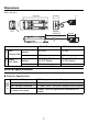
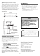
75[2.95]
75[2.95]
EXT*