
User guide

5
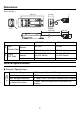
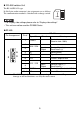
RS-485 Isolation Unit
The RS-485/RS-422 type.
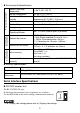
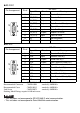
D-Sub 9-pin socket connector's pin assignments are as follows.
The communication method is switched with a change switch.
• For Display side settings please refer to “Display side settings”.
• This unit can not be used for GP4000 Series.
RS-485
Pin Arrangement Pin #
RS-485
Signal Name Direction Meaning
1TRMRX -
Termination
(Receive side: 100Ω)
2
RDA / SDA
--
3
Input /
Output
Receive Data A(+) /
Send Data A (+)
4 NC - No connection
5 SG - Signal Ground
6VCC -
+5V
±5% output 0.05A
*1
*1 The VCC output for Pin #6 is not protected against overcurrent. To prevent
damage or unit malfunctions, use only the rated current.
7
RDB / SDB
--
8
Input /
Output
Receive Data B(-) /
Send Data B(-)
9 TRMTX - Termination (Send side: 100Ω)
Shell FG - Frame Ground
RS422
RS485
5
1
6
9