
User Manual

Chapter 2 Specifications
2-27
2.2.3 Interface Specifications
This section describes the specifications of each interface of the PS-3711A Series unit.
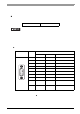
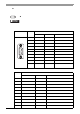
Serial Interface (COM1,COM2)
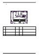
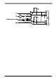
The PS-A unit side connector is a D-Sub 9 pin plug type.
COM1
Interfit Bracket #4-40 (UNC)
• Do not conne c t an y pi n s t o CO M2 [NC ] .
• Connect the FG terminal line to the shell.
• Always connect the #5 SG (Signal Ground) of the PS-A unit to the connected
device, especially if the connected device is also not isolated. Fa ilure to do so
may damage the RS232C/RS422/RS485 circuit.
• FG and SG terminals are internally connected in the PS-A. When connecting to
another device, be sure not to create an SG shorting loop in your system.
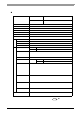
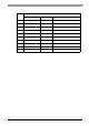
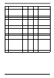
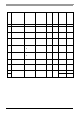
Pin Arrangement Pin No.
RS-232C
Signal Name Directi on Meaning
1 CD Input Carrier Detect
2 RD(RXD) Input Receive Data
3 SD(TXD) Output Send Data
4 ER(DTR) Output Data Terminal Ready
5 GND(SG) - Signal Ground (SG)
6 DR(DSR) Input Data Set Ready
7 RS(RTS) Output Request to Send
8 CS(CTS) Input Clear to Send
9CI(RI)/+5V
*1
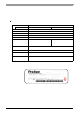
*1 To change the RI/+5V setting of #9 pin, open the PS-A unit's rear cover and set
slide switch to the desired position.
Please refer to Switches (page 2-30) for details.
Input / Output
Called status display / +5V
Output (Switching available)
FG FG -
Frame Ground
(Common with SG)
9
6
5
1
(PS-A side)