
User Manual


Chapter 2 Specifications
2-17
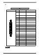
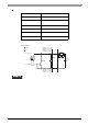
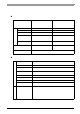
General-Purpose Output (DOUT 0 to 3)
Rated Voltage DC1 2V to 24V
Maximum Load Current 120mA/point
Out Voltage Drop
1.5V or less
(at 100mA load curr en t)
Output Points 4 points
Isolation Method Photocoupler Isolation
Dielectric Strength
Voltage
500V or more
External Power Supply DC12V / 200mA, DC5V / 100mA
• Be sure to operate the unit within its maximum load current. If the maximum load
current exceeds this range, a malfunction or PS-A damage may occur.
• Design your electrical system by adding the load current and voltage values to
the terminal voltage. If load current value used is large, the voltage drop of 1.5V
or less will occur between the terminals.
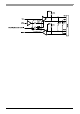
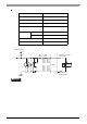
• When connecting an induction load, be sure to connect the above drawing's pro-
tection diode (*1).
+5V
R
PC357
4.7kΩ
SSTA06
Cable
*
1
DC12V
to
24V
DOUT2(+) pin # 8
DOUT0(+) pin # 10
DOUT1(+) pin # 20
DOUT3(+) pin # 22
DOUT2(-) pin # 7
DOUT0(-) pin # 9
DOUT1(-) pin # 19
DOUT3(-) pin # 21
( Interface Circuit )
Load