
User Manual

Chapter 2 Specifications
2-11
Switches
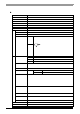
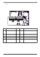
The following switch settings corresponding to each Serial Interface need to be signified. To set the switches
which are on the PS-A’s circuit board, remove the PS-A’s Rear Cover. Please refer to "3.2.1 Removal/
Attachment the Rear Cover" (page 3-6). The switches are lo ca ted as follows;
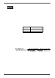
Switch
Location
Switch Name
Compatible
I/F
Factory
Settings
Description
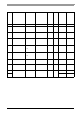
A Serial Mode Select SW COM3
All OFF
(RS-232C)
10-point dip switch. Designates COM3
communication settings. For Serial Mode
Select SW details, see Table (2).
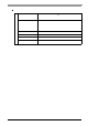
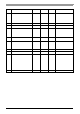
B System Set SW -
See
Tabl e ( 1)
10-point dip switch. For System Set SW and
the factory settings det ails, see Table (1).
C RI/+5V Changeover SW COM1 RI Changes # 9 pin (RI <---> +5V).
D RI/+5V Changeover SW COM2 RI Changes # 9 pin (RI <---> +5V).
E
Touch Panel's Communication
Changeover SW
COM4
USB
USB
Changes the Touch Panel communication
method. (Serial <---> USB)
(If “Serial” is selected, COM4 cannot be used.)
ON
123456789
10
10
ON
123456789
RI
AB
CD
E
5V RI 5V
USB RS232C
Inside of the rear