
User Manual

PL3000 Series Hardware Manual
3-10
3.3 Interface Specifications
This section describes the specifications of each interface of the PL Series unit.
Serial Interfaces
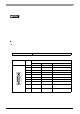
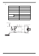
Serial Interfaces (COM1)
This interface is used to connect an RS-232C/RS-422/RS-485
*1
serial cable. A D-sub 9-pin plug connector is
used.
RS-232C
• This PL unit’s serial port is not isolated. Always connect the #5 SG (Signal
Ground) of the PL unit to the connected device, especially if the connected device
is also not isolated. Failure to do so may damage the RS232C/RS4 22/RS485
circuit.
• The SG (signal ground) and FG (frame ground) terminals are connected
internally in the PL unit. When connecting the SG line to another device, be sure
that the design of the system/connection does not produce a shorting loop.
• Connect FG terminal line to housing.
• Do not connect any pins to COM1 [NC].
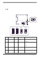
*1 To change the communication method, set the DIP switch located on the circuit board in the PL
unit to the desired position. The factory setting is RS-232C. Please refer to “3.4 Internal Switch-
es Specifications” (page 3-16).
*2 To change the CI (RI)/+5V setting of pin #9, set the slide switch located on the circuit board in
the PL unit to the desired position. Please refer to “3.4 Internal Switches Specifications” (page
3-16).
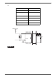
Interfit Bracke t #4-40 (UNC)
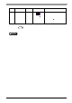
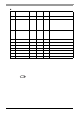
Pin Arrangement Pin No.
RS-232C
Signal Name Direction Description
1 CD Input Carrier Detect
2 RD(RXD) Input Receive Data
3 SD(TXD) Output Send Data
4 ER(DTR) Output Data Terminal Ready
5SG
-
Signal Ground
6 DR(DSR) Input Data Set Ready
7 RS(RTS) Output Request to Send
8 CS(CTS) Input Clear to Send
9 CI(RI)/+5V Input/
-
Called status display
+5V Output 0.5A
*2
Shell FG
-
Frame Grou nd
(Common with SG)
(PL unit sid e)
9
6
5
1