
User Manual


Chapter 5 Installation and Wiring
5-25
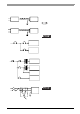
Connecting the Power Cord
(1) Confirm that power is not supplied to the PL unit.
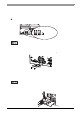
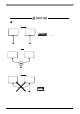
(2) Push the Opening button with a small slot screw driver to open the desired pin hole.
(3) Insert each pin terminal into its designated hole. Release the opening button to clamp the pin place.
(4) After inserting all three pins, insert the power plug into the power connector at PL. Fix the plug with two
(2) slot screws.
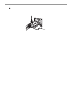
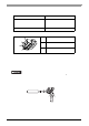
Screw-type Power Connector
When the DC type PL3000B series unit is installed vertically, use the screw-type
DC power supply connectors (right-angled). Use the following procedure to
connect a screw-type power connector to DC power supply units :
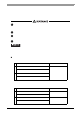
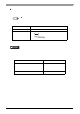
Power Cord Specifications
• Confirm that all wires are connected correctly.
• The torque required to tighten these screws is 0.5 to 0.6 N•m.
• To prevent the possibility of a terminal short, use a pin termin al that has an
insulating sleeve.
SEE
Power Connector (page 5-23)
Power Cord Diameter 0.75 to 2.5mm
2
(18-12 AW G)
Conductor Type Solid or stranded Wire
*1
*1 If the conductor’s end (individual) wires are not twisted correctly, they may short
against each other or an electrode.
Conductor Length
• Use copper conductors only.
• Temperature rating of field installed conductors: 75°C only.
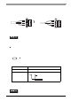
24V
0V
FG
L
N
FG
Opening Button
Black
White
Green/Yellow
AC power supply cable
Opening ButtonDC power supply cable
7mm [0.28in.]