
User Manual


Chapter 3 PL Monitoring Features
3-7
External Output Signal
The PL’s RAS interface connector uses the following output signals.
• General-Purpose Output (DOUT 2 bits)
This general purpose digital output signal provides system condition information to external devices.
The System Monitor property of the control panel or the API-DLL is used by applications to control this
signal.
The above mentioned general purpose digital output signals provide system condition information to
external devices.
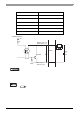
• General-Purpose Input (DIN) level mu st be 1.5 seconds or longer to be detected. It
may not detect under 1.5 seconds.
• Be sure the voltage value between terminals is controlled via the input voltage, so
that the PL is operated within its recommended range. If the input voltage exceeds
this range, a malfunction or PL damage may occur.
• With Sink/Source input, even if the D(-), and RESET(-) are positive, and D(+),
RESET(+) are negative, no problems are created. Be sure to operate the unit within
the recommended voltage range.
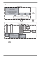
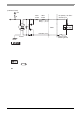
• For connection pin location details,
(Interface Circuit)
+5V
1.8k
Ω
1/10W
1.8k
Ω
1/10W
R
R
PC357
No polarity - for Sink /
Source input
switch or other
switching device
Cable
DC12V
to 24V
DINCOM pin # 9
DIN0(+) pin # 4
DIN1(+) pin # 5
SEE
PL3000 Series Hardware Manual “Specifications”