
User Manual


PL3000 Series Reference Manual
3-6
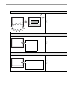
LED Indicator
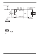
External Input Signals
The PL’s RAS interface connector uses the following input signals.
• General-Purpose Input (DIN 2 bits)
This standard digital input is used for error/alert detection in external devices. The input signal uses two bits.
The System Monitor property of the control panel or the API-DLL can be used to enable or disable this
feature, as well as designate what type of processing is to be performed once a signal is received. (Only
the “ON” state of the DIN circuit is detected. The “OFF” state of the DIN circuit cannot be monitored.)
• Remote Reset Input
This is the reset si gnal sent from an external device to the PL. When this signal is enabled, a forced reset
of the PL is performed.
The System Monitor property of the control panel or the API-DLL can be used to enable or disable this
feature.
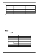
LED Color System Status output condition
Green (Lit) Normal Operation (Power is ON) None
Green (Blinking) System is NOT running (Soft OFF) None
Orange (Lit) A RAS error/alert occurred.
LED is enabled via System
Monitor Property.
Orange/Red (Blinking) Backlight burnout is detected. None
Not Lit Power is OFF -
• To enable Remote Reset Input, make sure to check the [Enable] in the Remote reset tab of
System Monitor Property. For Remo te rese t of System Monitor Property, refer to the following.
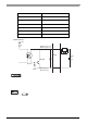
Input Voltage DC12V to 24V
Input Method Sink / Source Input
Input Current 10mA (DC24V)
Input Resistance 3.6kΩ
Input Points
2 points (common with external reset
input)
Operation Range
ON voltage DC10V or more
OFF voltage DC3V or less
Isolation Method Photocoupler Isolation
Dielectric Strength Voltage 500V or more
SEE
2.2.2 Advanced (page2-7)
3.8.5 Remote reset (page3-35)