
User Manual


PL3000 Series Reference Manual
A-4
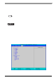
3Interrupt Map
APIC MODE
Interrupt
Level
Description No.
Expansion
Slot
Remark
Setting
Change
NMI Parity Error or I/O Channel Check
IRQ0 System Timer
IRQ1 Keyboard
IRQ2 Slave PIC Cascade
IRQ3 COM2 Possible
IRQ4 COM1 Possible
IRQ5 SMBUS
IRQ6 Reserved Possible
IRQ7 Available for users Possible
IRQ8 Real Time Clock
IRQ9 ACPI
IRQ10 COM4 Possible
IRQ11 COM3 Possible
IRQ12 Reserved
IRQ13 Coprocessor
IRQ14 Primary IDE
IRQ15 Secondary IDE
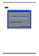
IRQ16
USB UHCI #3 (Reserved)
Display adapter
INTA
IRQ17 PCI express INTB SLOT#1
*1
*1 When an expansion slot supporting PCIe is included, the setting can be changed from the BIOS set-
up menu.
The table above shows the allocation in the APIC mode. The PL unit is set to the APIC mode by de-
fault.
PCIe Type
*1
IRQ18 USB UHCI #2 (Reserved) INTC
IRQ19 USB UHCI #1 (Port3, 4) AHCI INTD USB 3/4 Port
IRQ20 Built-in LAN2 INTE SLOT#0
IRQ21 Available for users INTF SLOT#1
IRQ22 HDAudio INTG SLOT#2 Possible
IRQ23
USB EHCI (USB 2.0)
USB UHCI #0 (Port1, 2)
INTH SLOT#3 USB 1/2 Port