
User Manual

PS-3710A Series Hardware Manual
3-8
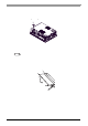
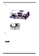
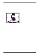
3.2.3 Attaching the Power Switch cover
For the AC type to conform to ANSI/ISA standards, th e Power Switc h cover ne eds to be at tached to the main
unit.
The necessary torque is 0.5N
•m to 0.6N•m.
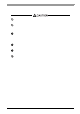
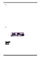
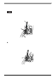
3.2.4 Main Memory Installation
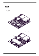
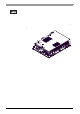
(1) Remove the PS-A unit's rear cover.
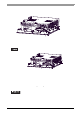
(2) Angle the main memory module down slightly, and push it in until the connector pins mate with the
module's pins. Then, lower the module until it is horizontal and insert it completely into the connector.
This connector is shown in 3.2.2 PS-A Internal View.
(3) Push in the main memory module until the stopper snaps into place.
SEE
“3.2.1 Removal/Attachment the Rear Cover” (page 3-7)
Connector
Main Memory
Stopper
(2)
(3)