
User Manual


Chapter 2 Specifications
2-9
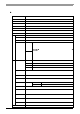
COM3
COM3 can be changed to either RS-232C, RS-422 or RS-485. (The factory setting is RS-232C.) To change
this setting, open the PS-A unit's rear cover and set slide switch on the circuit board to the desired position.
SEE
Switches (page 2-11)
• Be sure to confirm what settings will be used by the other device and set the slide
switches accordingly. Failure to do so can result in a unit malfunctio n or damage .
• Whenever changing the PS-A switches, be sure to first turn the PS-A's power
supply OFF. Failure to do so can cause a PS-A malfunction .
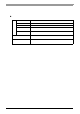
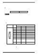
Pin Arrangement Pin No.
RS-232C
Signal Name Direction Meaning
1 CD Input Carrier Detect
2 RD(RXD) Input Receive Data
3 SD(TXD) Output Send Data
4 ER(DTR) Output Data Terminal Ready
5 GND(SG) - Signal Ground (SG)
6 DR(DSR) Input Data Set Ready
7 RS(RTS) Output Request to Send
8 CS(CTS) Input Clear to Send
9 CI(RI) Input Called status display
FG FG -
Frame Ground
(Common with SG)
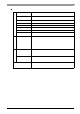
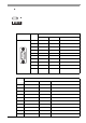
Pin No.
RS-422
Signal Name Direction Meaning
1 RDA Input Receive Data A (+)
2 RDB Input Receive Data B (-)
3 SDA Output Send Data A (+)
4 NC - No Connection
5 GND - Signal Ground (SG)
6 NC - No Connection
7 SDB Output Send Data B (-)
8 NC - No Connection
9 NC - No Connection
FG FG - Frame Ground (Common with SG)
9
6
5
1
(PS-A side)