36 $ 6HULHV +DUGZDUH 0DQXDO
Preface Thank you for purchasing Pro-face’s PS-3710A Series (Hereafter referred to as the “PS-A unit”). Before operating your PS-A unit, be sure to read this manual to familiarize yourself with the PS-A unit’s operation procedures and features. NOTICE 1. Copying this manual’s contents, either in whole or in part, is prohibited without the express permission of Digital Electronics Corporation, Japan. 2. The information contained in this manual is subject to change without notice. 3.
Essential Safety Precautions All safety-related procedures stated in this document must be followed to operate the PS-A correctly and safely. Be sure to read this and any related documents thoroughly to understand the correct operation and functions of the PS-A unit. Safety Icons Throughout this manual, these icons provide essential safety information for PS-A operation procedures requiring special attention.
Do not use the PS-A with aircraft control devices, aerospace equipment, central trunk data transmission (communication) devices, nuclear power control devices, or medical life support equipment, due to these devices’ inherent requirements of extremely high levels of safety and reliability. Be sure to design your system so that a communication fault between the PS-A and its host controller will not cause equipment to malfunction. This is to prevent any possibility of bodily injury or equipment damage.
Installation Be sure all cable connectors are securely attached to the PS-A unit. A loose connection may cause incorrect input or output signals. Wiring Be sure to ground the PS-A unit’s FG wire separately from other equipment FG lines. Also, be sure to use a grounding resistance of 100Ω or less and a 2mm2 or thicker wire, or your country’s applicable standard. Otherwise, electric shock or malfunctions may result. Be sure to use only the designated torque to tighten the PS-A unit’s terminal block screws.
Do not operate or store the PS-A in locations where it can be exposed to direct sunlight, high temperatures, excessive dust, moisture or vibration. Do not operate or store the PS-A where chemicals evaporate, or where chemicals are present in the air. Corrosive chemicals: Acids, alkalines, liquids containing salt Flammable chemicals: Organic Solvents Do not use paint thinner or organic solvents to remove dirt or oil from the PS-A unit’s surface.
• To prevent an afterimage: * Set the PS-A unit’s display OFF feature when you plan to display the same screen image for a long period of time. * Change the screen image periodically and try to not display the same image for a long period of time. Information Symbols This manual uses the following icons: Indicates a warning or a product limitation. Be sure to follow the instructions given with this icon to ensure the safe operation of the PS-A. * Indicates useful or important supplemental information.
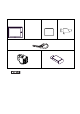
Package Contents The following items are included in the PS-A unit’s package. Before using the PS-A, please check that all items listed here are present. PS-A Unit: 1 • Installation Guide Installation Gasket: 1 (Attached to the PS-A unit) Installation Fasteners: 4 per set x2 • Warning/Caution Information (1) USB Cable Clamp: (2ports) 2 Power Connector: 1 Power Switch cover (1 set) (cover:1, secrew:1) • Be careful when installing the PS-A not to damage the built-in HDD.
Installation prerequisites for standards • UL listed products Industrial Control Equipment refer to UL508 see [a] in the “Product List“ Suitable for use in Class I, Division 2, Groups A, B, C, and D Hazardous (classified) locations, or Non-Hazardous Locations. refer to ANSI/ISA 12.12.01 see [b] in the “Product List“ Process Control Equipment refer to CSA-C22.2 No.
• Suitable for use in Class I, Division 2, Groups A, B, C, and D Hazardous Locations only. • WARNING: Explosion hazard - substitution of components may impair suitability for Class I, Division 2. • WARNING: Explosion hazard - do not disconnect equipment while the circuit is live or unless the area is known to be free of ignitable concentrations.
CE Marking PS3710A-T41-PA1/PS3710A-T42-PA1 units are CE marked, EMC directives and Low Voltage Directive compliant products. They comply with EN61000-6-4 , EN61000-6-2 and EN60950-1. FCC Statement United States FCC Part 15, Subpart B, Class A EMI Compliance Statement: NOTE: This equipment has been tested and found to comply with the limits for a Class A digital device, pursuant to part 15 of the FCC Rules.
Contents Preface ...................................................................................................................... 1 Essential Safety Precautions..................................................................................... 2 Information Symbols.................................................................................................. 6 About the Manuals ....................................................................................................
3.2.7 HDD/SSD Unit Installation ..................................................................................3-12 3.2.8 CF Card Insertion/Removal ................................................................................3-13 3.2.9 USB Cable Clamp Attachment/Removal ............................................................3-15 3.2.10 Attach the PS-A unit to an Arm .........................................................................3-17 3.3 Wiring Precautions...............................
1 Overview 1. System Design 2. Accessories 3. Part Names and Functions This chapter describes peripheral devices that can be connected to PS-A Series units along with the name and functions of each part.
PS-3710A Series Hardware Manual 1.1 System Design 1.1.1 PS-3710A Series Bottom of PS-A unit Side of PS-A unit PS3710A-T41-PA1 Inside of PS-A unit The following diagram illustrates the standard range of items that can be connected to PS-3710A Series.
Chapter 1 Overview 1.2 Accessories All accessories listed here are produced by Digital Electronics Corporation. 1.2.1 Option Items Product Name DIM module Model No. PSA-DDR512 PSA-DDR1G PS365XA-HD40 Hard Disk Unit PS371XA-HD60P SSD Unit PS371XA-SD16P CA3-CFCALL/128MB-0 CA3-CFCALL/256MB-0 CA3-CFCALL/512MB-0 CA6-CFCALL/1GB-01 CF Card CF Card Adaptor 1.2.2 GP077-CFAD10 Description Memory module 512M Bytes Memory module 1G Bytes HDD Unit mounted is a Type 2.
PS-3710A Series Hardware Manual 1.3 Part Names and Functions 1.3.
Chapter 1 Overview K: USB Interface (USB) K R P UT V X Y 4 ports. Complies with USB 2.0. Uses a “TYPE-A” connector. L M NQ O S W Power supply voltage 5V DC ±5% Output current 500mA (max.) The maximum communication distance 5m Bottom L: Ethernet Interface (LAN1) 10BASE-T/100BASE-TX Auto Changeover. This interface uses an RJ-45 type modular jack connector (8 pins). M: Ethernet Interface (LAN2) 10BASE-T/100BASE-TX/1000BASE-T Auto Changeover.
PS-3710A Series Hardware Manual V: RAS Interface (RAS) D-SUB 25-pin plug type. W: Cooling FAN X: CF Card Interface Cover*1 CF card interface is under the cover. CF card (Type I / II-compliant) is available. IDE-type connection.*2 Y: Power Connector • When attaching peripheral units to the PS-A, be sure the PS-A’s power cord is disconnected from the main power supply. *1 For details on how to check the revision, See "About Revision" (page 10).
Chapter 1 Overview 1.4 Prior to Operating the PS-A Unit 1.4.1 Power Supply About states of PS-A’s power supply, there are three kinds of states, which are No Energization, Active State (Normal), and Soft OFF State*1. Each state is outlined in the following.
PS-3710A Series Hardware Manual 1-8
2 Specifications 1. PS-3710A Series This chapter describes the general, functional and interface specifications of the PS-A as well as its part names and dimensions.
PS-3710A Series Hardware Manual 2.1 PS-3710A Series 2.1.1 General Specifications Power Supply Electrical Specifications 2-2 Input Voltage AC100/240V Rated Voltage AC85 to 265V Rated Frequency 50/60Hz Allowable Voltage Drop 1 cycle or less (Voltage drop interval must be 1s or more.) Power Consumption 150VA or less Voltage Endurance AC1.500V 20mA for 1minute (between charging and FG terminals) Insulation Resistance DC500V 10MΩ(min.
Chapter 2 Specifications Electrical Mechanical Physical Environmental Specifications Surrounding Air Temperature 0 to 50°C: without HDD 5 to 50°C: with HDD Storage Temperature −20 to +60°C Ambient Humidity 10 to 90%RH (Not condensing, wet bulb temperature: 29°C or less.) Storage Humidity 10 to 90%RH (Not condensing, wet bulb temperature: 29°C or less.
PS-3710A Series Hardware Manual • When using any of the PS-A’s optional devices, be sure to check that device’s specifications for any special conditions or cautions that may apply to its use. • Be aware that not only does the Hard Disk/SSD have a fixed lifetime, but that accidents can always occur. Therefore, be sure to back up your Hard Disk/SSD’s data regularly, or prepare another Hard Disk unit that can be used for backup.
Chapter 2 Specifications Structural Specifications Installation Grounding Grounding resistance of 100Ω 2mm2 or thicker wire, or your country’s applicable standard. (Same for FG and SG terminals) Structure Rating: Equivalent to IP65f NEMA #250 TYPE 4X/12 (When installing Panels.) Feature size: All-in-one Installation configuration: Panel embedding Cooling Method Forced cooling by unit fan and CPU fan Weight Approx. 8.0kg [17.6lb] max. (unit only) External Dimensions W410mm [16.
PS-3710A Series Hardware Manual 2.1.2 Performance Specifications Performance Specifications CPU Intel® Pentium® M 1.6GHz (Banias) L2 Cache Memory 1M Bytes (Built in the CPU) Main Memory 2Slots (Max.2GB) SO-DIMM socket 256MB to 1GB (PC2700) Chipset Intel® 855GME GMCH and Intel® ICH-4 Graphic accelarator Build-in Intel® 855GME GMCH FirstBIOS Embedded Pro (Phoenix Technologies Co.) Graphics XGA (1,024 x 768 dots) Video Memory Max.
Chapter 2 Specifications DVD-ROM Drive*4 *5 Clock Accuracy Side Access, DVD-ROM Drive (connected to IDE Secondary) ±180 sec. /month (fudge factor by the situation temperature and power-off) *1 If “Serial” is selected, COM4 cannot be used. *2 To change the Master/Slave setting of Primary IDE I/F, set Serial Mode Select switch #9 pin on the circuit board to the desired position.
PS-3710A Series Hardware Manual 2.1.3 Interface Specifications This section describes the specifications of each interface of the PS-3710A Series unit. Serial Interface (COM1,COM2,COM3,COM4) The PS-A unit side connector is a D-Sub 9 pin plug type. Interfit Bracket #4-40 (UNC) • Do not connect any pins to COM3 [NC]. • Connect the FG terminal line to the shell. • Always connect the #5 SG (Signal Ground) of the PS-A unit to the connected device, especially if the connected device is also not isolated.
Chapter 2 Specifications COM3 COM3 can be changed to either RS-232C, RS-422 or RS-485. (The factory setting is RS-232C.) To change this setting, open the PS-A unit's rear cover and set slide switch on the circuit board to the desired position. Switches (page 2-11) SEE • Be sure to confirm what settings will be used by the other device and set the slide switches accordingly. Failure to do so can result in a unit malfunction or damage.
PS-3710A Series Hardware Manual RS-485 Pin No.
Chapter 2 Specifications Switches The following switch settings corresponding to each Serial Interface need to be signified. To set the switches which are on the PS-A’s circuit board, remove the PS-A’s Rear Cover. Please refer to 3.2.1Removal/ Attachment the Rear Cover (page 3-7).
PS-3710A Series Hardware Manual Switch No. Description ON OFF Factory Settings 1 Disable/enable Detecting the middle point during touching two points simultaneously.*1 Enabled Disabled OFF 2 Changes PIO/DMA of CF Card. PIO+DMA PIO ON 3 Changes PIO/DMA of CF Card. PIO+DMA PIO ON 4 Disable/enable Hardware Reset Switch. Disabled Enabled OFF 5 Able to change a Master/Slave setting for CF Card slot. Master Slave OFF*3 6 Disable/enable Access to the Front USB port.
Chapter 2 Specifications Switch No. Description ON OFF RS-485 RS-485 (Data is not (Data is automatiautomatically concally conRS-232C RS-422 trolled via the trolled via the RTS sigRTS signal.)*1 nal.)*1 1 Used by the system.
PS-3710A Series Hardware Manual Serial Mode Select Switches (SW4 to SW10) operate as shown in the circuit diagram below.*1 *1 To enable RTS automatic control of the TX output driver, be sure to set SW No. 9 and 10 ON, and set SW No.4 OFF. To enable control of the TX output driver via RTS signals, be sure to set SW No. 9 and 10 OFF, and set SW No.4 ON.
Chapter 2 Specifications RAS Interface The PS-A unit side connector is a D-Sub 25 pin plug type. Interfit Bracket Pin Arrangement 13 25 14 #4-40 (UNC) Pin No.
PS-3710A Series Hardware Manual General-Purpose Input (DIN 0 to 3, RST) Input Voltage DC12V to 24V Input Method Sink / Source Input Input Current 10mA ( DC24V ) Input Resistance 3.6kΩ Input Points 5 points ( common with external reset input ) Operation Range ON voltage DC10V or more OFF voltage DC3V or less Isolation Method Photocoupler Isolation Dielectric Strength Voltage 500V or more (Interface Circuit) +5V 1.8kΩ 1/10W R 1.
Chapter 2 Specifications General-Purpose Output (DOUT 0 to 3) Rated Voltage DC12V to 24V Maximum Load Current 120mA/point Out Voltage Drop 1.5V or less ( at 100mA load current ) Output Points 4 points Isolation Method Photocoupler Isolation Dielectric Strength Voltage 500V or more External Power Supply DC12V / 200mA, DC5V / 100mA ( Interface Circuit ) +5V DOUT2(+) DOUT0(+) DOUT1(+) DOUT3(+) R pin # pin # pin # pin # 8 10 20 22 Load *1 Cable SSTA06 DC12V to 24V PC357 4.
PS-3710A Series Hardware Manual Analog RGB Interface Mini D-Sub 15pin male. As an Analog RGB cable, commercial type or the one manufactured by Pro-face is available to use. Interfit Bracket Pin Arrangement 15 11 2-18 5 1 #4-40 UNC Pin No.
Chapter 2 Specifications 2.1.4 Dimensions The following dimensions apply to PS-3710A Series. Installation Fasteners Attached Dimensions Unit: mm[in.] Top 404.8[15.94] 382[15.04] 160[6.30] 160[6.30] +0.01 385+0.2 - 0.4 [15.16 - 0.02 ] 100[3.94] 4.3[0.17] 410[16.14] Left Side 303.8[11.96] +0.01 284+0.2 - 0.4 [11.18 - 0.02 ] 309 [12.17] 5[0.20] Right Side Front 160[6.30] 165[6.
PS-3710A Series Hardware Manual Cable Attached Dimensions Unit: mm[in.] Top 385[15.16] 79[3.11] 32.5[1.28] (Serial Interface) 46.5[1.83] (RAS Interface) 32.5[1.28] (USB Interface) Rear 9[0.35] (Line Input / Speaker Output / Mike Input Interface) Left Side 14.8[0.58] 284[11.18] 53.5[2.11] Right Side Bottom • All the above values are designed in case of cable bending. The dimensions given here are representative values depending on the type of connection cable used.
Chapter 2 Specifications Panel Cut Dimensions Unit: mm[in.] +0.04 +1 [15.20 ] −0 −0 4-R3[0.12] or less +1 +0.04 284.5−0 [11.20 −0 ] 386.1 Panel thickness area 1.6[0.06] to 10.0[0.39] • Please read "3.1.1 Installation (page 3-2)" before designing the Panel Cut. Installation Fasteners Unit: mm[in.] 11[0.43] 16[0.63] 16.6[0.65] 31[1.22] Φ10[0.
PS-3710A Series Hardware Manual 2-22
3 Installation and Wiring 1. Installation • Uninstallation 2. Peripheral Devices Installation 3.
PS-3710A Series Hardware Manual 3.1 Installation • Uninstallation 3.1.1 Installation This section describes the procedures and precautions for installing the PS-A units. Check the Installation Gasket’s Seating It is strongly recommended that you use the installation gasket, since it absorbs vibration in addition to repelling water. For the procedure for attaching the installation gasket, refer to “4.4 Replacing the Installation Gasket”. SEE “4.
Chapter 3 Installation and Wiring Installation Requirements • For easier maintenance, operation, and improved ventilation, be sure to install the PS-A at least 50 mm [1.97 in.] away from adjacent structures and other equipment. Unit: mm 50 50 50 50 50 50 • 50 Be sure that the ambient operation temperature and the ambient humidity are within their designated ranges.
PS-3710A Series Hardware Manual • When installing the PS-A in a slanted panel, and the panel face inclines more than 30°, the surrounding air temperature must not exceed 40°C. You may need to use forced air cooling (fan, A/C) to ensure the surrounding air temperature is 40°C or below. • The PS-A Series unit does not support longitudinal mounting. Installing the PS-A (1) Insert the PS-A into the panel cut, as shown. (2) Insert each fastener’s hook into the slot and tighten it with a screwdriver.
Chapter 3 Installation and Wiring (3) Insert each of the fasteners, as shown. Be sure to pull the fastener back until it is flush with the rear of the attachment hole. (4) Use a Phillips screwdriver to tighten each fastener screw and secure the PS-A in place. • Tightening the screws with too much force can damage the PS-A unit’s plastic case. • The torque required to tighten these screws is 0.5 N•m.
PS-3710A Series Hardware Manual 3.2 Peripheral Devices Installation A wide variety of optional units, DIM module, CF cards, manufactured by Pro-face and commercial Expansion boards (PCI bus compatible board), PCMCIA (PC cards) can be used with the PS-A. When installing the optional units, refer to each unit's “Installation Guide”. Be sure to confirm that power is not supplied to the PS-A unit before installing or removing any optional units, DIM module, CF cards, or Expansion boards (PCI boards).
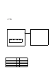
Chapter 3 Installation and Wiring 3.2.1 Removal/Attachment the Rear Cover • Use a screwdriver to loosen or tighten the screws. Be sure not to tighten screws too tightly, since it may damage the unit. • Be careful when removing or inserting any screws that they do not fall inside the PS-A. For PS-3710A Series Unscrew the five (5) attachment screws used to hold the Rear Cover in place, and remove the Rear Cover. The torque of the rear cover required for these screws is 0.5 to 0.6 N•m. 3.2.
PS-3710A Series Hardware Manual 3.2.3 Attaching the Power Switch cover For the AC type to conform to ANSI/ISA standards, the Power Switch cover needs to be attached to the main unit. The necessary torque is 0.5N•m to 0.6N•m. 3.2.4 Main Memory Installation (1) Remove the PS-A unit's rear cover. SEE (2) “3.2.1 Removal/Attachment the Rear Cover” (page 3-7) Angle the main memory module down slightly, and push it in until the connector pins mate with the module's pins.
Chapter 3 Installation and Wiring 3.2.5 Expansion Board (PCI) Installation • The Expansion Board (PCI) is corresponding to PS-3710A units. (1) Remove the PS-A unit's rear cover. SEE “3.2.1 Removal/Attachment the Rear Cover” (page 3-7) (2) Remove the blank panel’s screw, and detach the blank panel. (3) Insert the expansion board (commercial-type PCI) into the expansion board connector, and secure it in place using the filler panel’s screw. The necessary torque is 0.5N•m to 0.6N•m.
PS-3710A Series Hardware Manual • The maximum size allowed for an expansion board is 235mm x 106.68mm [9.25in. x 4.2in.]. When using an expansion board of this size, be sure to secure it in place using the expansion board support cover. Before the rear cover is closed, remove the expansion board support cover screw and be sure the expansion board support cover is detached.
Chapter 3 Installation and Wiring 3.2.6 PCMCIA Unit Installation (1) Remove the PCMCIA slot cover’s screws (2). PCMCIA Slot Cover (2) [Inserting a commercial-type PC Card] Insert the commercial-type PC Card into the PCMCIA connector. • The PCMCIA slot has 2 connectors. When the PS-A unit is placed as shown below, insert your PC Card with its face up. Eject Button PC Card (commercial) [Removing the PC Card] Press the eject button twice to remove the PC Card from the PCMCIA connector.
PS-3710A Series Hardware Manual 3.2.7 HDD/SSD Unit Installation Shock Danger! Be sure to unplug the PS-A unit from its power supply prior to installing the HDD unit. • Since the HDD/SSD unit is a precision instrument that has a low resistance to shocks, be sure it is neither hit by nor pressed strongly against another object when installing it. • Even when the PS-A unit’s screen display disappears, the power might be distributed inside (such as the “Standby” status etc.).
Chapter 3 Installation and Wiring 3.2.8 CF Card Insertion/Removal Prior to inserting or removing a CF Card, be sure to confirm that the PS-A unit is turned OFF. If you do not, CF Card internal data may be damaged or lost or the OS may stop. While a CF Card is being accessed (IDE Access Lamp: Lit in green), NEVER turn OFF or reset the PS-A, or insert or remove the CF Card. If you do not, CF Card internal data may be damaged or lost.
PS-3710A Series Hardware Manual When inserting the CF Card For PS-3710A Series (1) Unscrew the CF Card cover's attachment screw (1), and remove the CF Card cover. CF Card Cover (2) Insert the CF Card firmly into the CF card slot, and check that the eject button pops out. CF Card Eject Button Removing the CF Card For PS-3710A Series (3) Press the eject button in fully to remove the CF Card from the CF Card slot.
Chapter 3 Installation and Wiring Backup of CF Card The CF Card has a data overwrite limit of approximately 100,000 times. Therefore, be sure to back up all CF card data regularly to another storage media. (100,000 times assumes the overwriting of 500KB of data in DOS format.) < If your PC is equipped with a PC Card Slot > (1) Install the CF card into a CF Card Adapter (GP077-CFAD10) and insert it into a PC card slot of a personal computer.
PS-3710A Series Hardware Manual (2) As shown, insert the USB Cable Clamp’s band through the Bridge. Pass the USB cables through the Cable Clamp’s band and securely tighten the clamp band around the cables. • Be sure the clamp is securely holding the USB cable’s plug and collar. • Be sure the clamp is positioned as shown below, with the clamp pointing upwards - not to the side. This is to keep the clamp from interfering with nearby connectors and their cables.
Chapter 3 Installation and Wiring Attach the PS-A unit to an Arm To attach the PS-A unit to an Arm or to the wall, first remove the seal on the PS-A's rear face, then insert the attachment screws for a commercial-type arm or wall mount adaptor into the holes. (Holes specifications: VESA 75mm) For detailed attachment instructions, please refer to that product's installation guide. The VESA Arm Attachment Hole dimensions are signifies as follows; (unit: mm [in.]) 75 [2.95] 3.2.10 75 [2.
PS-3710A Series Hardware Manual 3.3 Wiring Precautions This section describes the procedures and precautions for wiring power cords. 3.3.1 Connecting the Power Cord To avoid an electric shock, prior to connecting the PS-A unit’s power cord terminals to the power terminal block, confirm that the PS-A unit’s power supply is completely turned OFF, via a breaker, or similar unit. Supplying a power voltage other than that specified will damage the power source and the PS-A unit.
Chapter 3 Installation and Wiring Wiring When connecting the power cord, use the following items when performing wiring. (Items are made by Phoenix Contact.*1) Recommended Driver SZS 0.6x3.5 (1205053) Recommended Pin Terminals AI 0.75-10GY (3201288) AI 1-10RD (3200182) AI 1.5-10BK (3200195) AI 2.5-12BU (3200962) Recommended Pin Terminal Crimp Tool CRIMPFOX ZA3 (1201882) • The power connector (plug) is FKC 2.5/3-STF-5.08 made by Phoenix Contact.
PS-3710A Series Hardware Manual 3.3.2 Connecting the Power Supply This section describes the precautions for supplying a power voltage. Twisted-pair cord PS-A Constant Voltage FG • If the supplied voltage exceeds the PS-A unit’s range, connect a constant voltage transformer. SEE Twisted-pair cord Insulating Transformer Chapter 2 "Specifications" • For between the line and ground, select a power supply PS-A FG that is low in noise.
Chapter 3 Installation and Wiring 3.3.3 Grounding This section describes the precautions for grounding the PS-A unit. Do not use common grounding, since it can lead to an accident or machine breakdown. (a) Exclusive Grounding (BEST) • When supplying power to the PS-A unit, be sure to separate the Other Equipment PS-A input/output and power lines, as shown. [diagram (a)] • Check that the grounding resistance is 100Ω or less. • FG and SG terminals are internally connected in the PS-A.
PS-3710A Series Hardware Manual 3-22
4 Maintenance 1. Cleaning the Display 2. Cleaning the Fan Filter 3. Periodic Check Points 4. Replacing the Installation Gasket 5. Replacing the Backlight 6. Replacing the Internal Battery This chapter explains cautions and inspection criteria that will ensure trouble-free use of the PS-A.
PS-3710A Series Hardware Manual 4.1 Cleaning the Display When the surface or frame of the display become dirty, soak a soft cloth in water with a neutral detergent, wring the cloth tightly, and wipe the display. • Do not use paint thinner, organic solvents, or a strong acid compound to clean the unit. • Do not use hard or pointed objects to operate the touch-screen panel, since it can damage the panel surface. 4.
Chapter 4 Maintenance 4.3 Periodic Check Points To keep your PS-A unit in its best condition, please inspect the following points periodically. PS-A Operation Environment Is the operating temperature within the allowable range? PS-3710A: 0°C to 50°C (without HDD) 5°C to 50°C (with HDD) Is the operating humidity within the specified range? PS-3710A: 10 to 90%RH (Not condensing, wet bulb temperature: 29°C or less.
PS-3710A Series Hardware Manual 4.4 Replacing the Installation Gasket The installation gasket provides protection against dust and moisture. • A gasket which has been used for a long period of time may have scratches or dirt on it, and could have lost much of its water resistance. Be sure to change the gasket at least once a year, or when scratches or dirt become visible. • The PS-A unit installation gasket’s model number is CA3-WPG15-01-PA1.
Chapter 4 Maintenance • The gasket must be inserted correctly into the groove for the PS-A’s moisture resistance to be equivalent to IP65f. • Since the gasket is flexible but not elastic, be careful not to stretch it unnecessarily, as doing so could tear the gasket. • Be sure the gasket’s seam is not inserted into any of the unit’s corners, only in the straight sections of the groove. Inserting it into a corner may lead to its eventually tearing.
PS-3710A Series Hardware Manual 4.5 Replacing the Backlight • The backlights of the PS-A which is marked on Rev.5 cannot be replaced by the user. When the backlight needs to be replaced, please contact your local PS-A distributor. About the Backlight PS-A units use a CFL, long-life type backlight. The actual life of the backlight however, will vary depending on the PS-A’s operating conditions. It is recommended that it be replaced periodically. A PS-A backlight has a life of 50,000 hours (approx. 5.
Chapter 4 Maintenance Preparation Please have the following ready beforehand. • • • Replacement backlight One pair of clean (preferably new) cotton gloves. Phillips screwdriver (no.2) • The appropriate replacement backlight depends on your PS-A model. PS-A 4.5.
PS-3710A Series Hardware Manual (5) Insert a screwdriver into the two holes (points) shown below, and remove the backlight attachment screws (1 per hole). FD Drive unit Insertion Area Insert a screwdriver (2 holes) DVD-ROM Drive (6) Remove the cable from the cable clamp, and detach the cable from the backlight connector on the inverter board.
Chapter 4 Maintenance (7) Pull out the cable in the direction shown by the arrow. The backlight unit detaches from the backlight unit insertion point. Backlight Unit Cable Backlight Unit Insertion Point • The entire backlight unit should be changed, not just the backlight. (8) Insert the new backlight unit into the backlight holder. (9) Re-attach the cable to the backlight connector, and secure the cable in position using the cable clamp (opposite of step (6)).
PS-3710A Series Hardware Manual 4.6 Replacing the Internal Battery The PS-A unit has an internal battery for backup of internal clock data. Compatible Battery Service Life Lithium Battery CR2032 (Hitachi Maxell, Ltd.) 5 years • The expected battery service life is 5 years, however the battery may die before then. It is strongly recommended that you replace the battery regularly. • When the battery is replaced, a part of the BIOS settings are initialized.
Chapter 4 Maintenance Battery Replacement Procedure The battery is on the PC board inside the PS-A unit. Refer to ““3.2.1Removal/Attachment the Rear Cover” (page 3-7)” for how to open the PS-A unit. (1) Be sure to confirm that power is not supplied to the PS-A unit and open the unit. Internal Battery Internal View (2) Remove the battery. Push the clip of the battery holder with your finger, the forceps etc. and the battery is pushed up and removed.