
User Manual

13
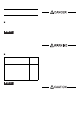
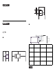
COM1
*3 To change the communication method, set
the DIP switch located on the ci rcui t board in
the PL unit to the desired positi on .
For details, see [Interna l Switches].
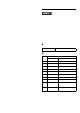
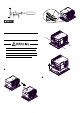
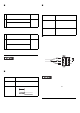
RAS Interface
• Be sure to use only the rated voltage
level when using pin #1 (+12V) for
external power output. Failure to do so
can lead to a unit malfunction or acci-
dent.
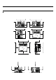
• For the circuit diagram, refer to “PL3000
Series Reference Manual”.
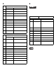
Pin #
RS-422
*3
Signal Name
Description
1 RDA Receive Data A(+)
2 RDB R e c eive Data B(-)
3 SDA Send Data A(+)
4ERA
Data Terminal Ready
A(+)
5 SG Signal Ground
6 CSB Clear to Send B(-)
7 SDB Send Data B(-)
8 CSA Clear to Send A(+)
9ERB
Data Terminal Ready
B(-)
Shell
FG
Frame Ground
(Common with SG)
Pin #
RS-485
*3
Signal Name
Description
1DATA +
Send/Receive Data
(+)
2DATA -
Send/Receive Data
(-)
3 NC No Connection
4 NC No Connection
5 SG Signal Ground
6 NC No Connection
7 NC No Connection
8 NC No Connection
9 NC No Connection
Shell
FG
Frame Ground
(Common with SG)
Interfit Bracket #4-40 (UNC)
Pin #
Signal Name
Description
1 +12V
Output Current:
100mA or less
Output Voltage:
12V
±
5%
2 DOUT0(+) Data out 0(+)
3 DOUT1(+) Data out 1(+)
4 DIN0(+) Data in 0(+)
5 DIN1(+) Data in 1(+)
*1
*1 Can be used as reset input.
6 GND Ground
7 DOUT0(-) Data out 0(-)
8 DOUT1(-) Data out 1(-)
9 DINCOM
Data in ground
common