
User Manual

12
• Avoid leaving the bat tery in high tem-
perature places such as direct sunlight,
inside a sun-heated car, near water, or
near a heater. Doing so may cause
battery leakage, or reduce the battery
functions and lifetime.
• The battery can be recycled. To recycle
your used battery, fo llow the regula-
tions and instructions in your area.
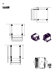
External Interfaces
• This PL unit’s serial port is not iso lated.
When the host (PLC) unit is also not
isolated, and to reduce the risk of dam-
aging the RS-232C/RS-422/RS-485
circuit, be sure to connect pin #5 SG
(Signal Ground) terminal.
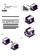
• Never connect NC to COM1.
• Connect FG to housing.
• COM2 is not available on the built-in
battery unit version because tha t ver-
sion uses COM2 exclusively as an
interface for battery output.
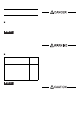
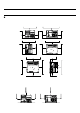
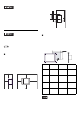
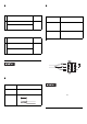
Serial Interface
(COM1, COM3, COM4)
COM1, COM3, COM4
Interfit Bracket #4-40 (UNC)
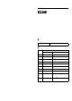
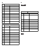
Pin #
RS-232C
Signal Name
Description
1 CD Carrier Detect
2 RD(RXD) Receive Data
3 SD(TXD) Send Data
4 ER(DTR) Data Terminal Ready
5 SG Signal Ground
6 DR(DSR) Data Set Ready
7 RS(RTS) Request to Send
8 CS(CTS) Clear to Send
9CI(RI)/+5V
Called status display/
+5V Output 0.5A
*1
*2
*1 Only CO M1 is availabl e for switching to +5 V.
COM3 and COM4 are used exclusive ly for CI
(RI).
*2 Slide switch on the circuit board in the PL unit
switches between CI (RI) and +5 V. For
details, see [Internal Switches].
Shell
FG
Frame Ground
(Common with SG)