
User Manual
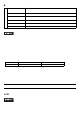

9
External Interfaces
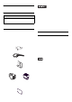
• Always connect the #5 SG (Signal
Ground) of the PL unit to the con-
nected device, especially if the con-
nected device is also not isol ated.
Failure to do so may damage the RS-
232C/RS-422/RS-485 circuit.
• Never connect NC to COM1.
• Connect FG to housing.
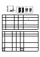
Serial Interface
(COM1, COM2, COM3, COM4)
COM1, COM2, COM3, COM4
COM1
*3 To change the communication method, set
the DIP switch lo cated o n the cir cuit b oard in
the PL unit to the desired position.
For details, see [Internal Switches].
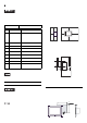
Interfit Bracket #4-40(UNC)
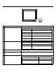
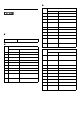
Pin #
RS-232C
Signal Name
Description
1 CD Carrier Detect
2 RD(RXD) Receive Data
3 SD(TXD) Send Data
4 ER(DTR) Data Terminal Ready
5 SG Signal Ground
6 DR(DSR) Data Set Ready
7 RS(RTS) Request to Send
8 CS(CTS) Clear to Send
9CI(RI)/+5V
Called status display/
+5V Output 0.5A
*1
*2
*1 Only COM1 and COM2 are available for
switching t o +5 V . COM3 and COM 4 are used
exclusively for CI (RI).
*2 Slide switch on th e circuit board in the PL un it
switches between CI (RI) and +5 V. For
details, see [Internal Switches].
Shell
FG
Frame Ground
(Common with SG)
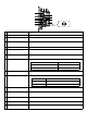
Pin #
RS-422
*3
Signal Name
Description
1 RDA Receive Data A(+)
2 RDB Receive Data B(-)
3 SDA Send Data A(+)
4ERA
Data Terminal Ready
A(+)
5 SG Signal Ground
6 CSB Clear to Send B(-)
7 SDB Send Data B(-)
8 CSA Clear to Send A(+)
9ERB
Data Terminal Ready
B(-)
Shell
FG
Frame Ground
(Common with SG)
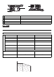
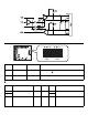
Pin #
RS-485
*3
Signal Name
Description
1DATA +
Send/Receive Data
(+)
2DATA -
Send/Receive Data
(-)
3 NC No Connection
4 NC No Connection
5 SG Signal Ground
6 NC No Connection
7 NC No Connection
8 NC No Connection
9 NC No Connection
Shell
FG
Frame Ground
(Commo n w i th SG )