
User Manual

8
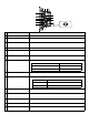
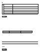
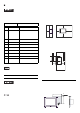
Serial Mode Select Switches (SW4 to SW10) operate as shown in the circuit diagram below.
*1 Refer to *2 on the previous page.
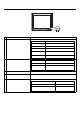
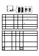
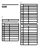
2. Internal switches of the front module
Touch Panel Set Switch
Switch
Location
Switch Name
Factory
Settings
Description
SW1
Touch Panel
Set Switch
1:ON, 2:ON,
3:OFF, 4:OFF
4-point DIP switch. For Touch Panel Set Switch
details, see “ Touch Panel Set Switch”.
SW2 —
1:OFF, 2:OFF,
3:ON, 4:OFF
Internal setting.
Do not change. (Factory setting)
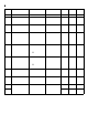
Switch
No.
Description ON OFF
Factory
Settings
Notes
1 to 2
Internal setting
Reserved Reserved
ON
Do not change.
(Factory setting)
3OFF
4
Cancellation function
of two point touch on
the touch panel
*1
*1 When two points are p ushed , it is co nside red that mi ddle point b etwe en the two po ints is touched
according to t he nature of the ana log re sistive t ouch p anel. Whe n the swi tch, etc. i s set on th e middl e
point, it w ill be enabled and may operate. To prevent such a sw itch from malfunction in case of pushing
two points, turn ON the Switch No.4 in advance, then the middle point will be disabled for two point
touch.
Enabled Disabled
OFF
The midd le point is not considered
to be touched when the switch is
ON. It is considered to be touched
when the switc h is OF F.
*1
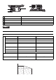
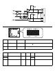
RT(RTS) Automatic
control
SW1
SW2
ON
ON
Rear face of the front module