
User Manual

6
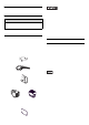
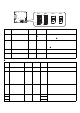
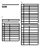
1. Internal switches of the control box
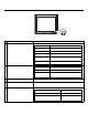
System Set Switch
Switch
Location
Switch Name
Compati-
ble I/F
Factory
Settings
Description
SW1 System Set Switch –
See
System
Set Switch
10-point DIP switch. For System Set
Switch and the factory settings
details, see System Set Switch.
SW2
Serial Mode Select
Switch
COM1
All OFF
(RS-232C)
10-point DIP switch. Designates
COM1 communication settings. For
Serial Mode Select Switch details,
see Serial Mode Select Switch.
SW3
CI(RI)/+5V
Changeover Switch
COM2 CI(RI) Changes # 9 pin (CI(RI) / +5V).
SW4
CI(RI)/+5V
Changeover Switch
COM1 CI(RI) Changes # 9 pin (CI(RI) / +5V).
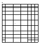
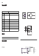
Switch
No.
Description ON OFF
Factory
Settings
Notes
1 Internal setting
Reserved Reserved
OFF
Do not change.
(Factory setting)
2
Implements the
logical inversion
operation for
RAS output
Normal
Close
Normal
Open
OFF
RAS output is a CLOSE state when the
switch and the system is ON. Wh en the
Switch is OFF, it is the opposite. The
RAS Output keeps No rmal OPEN
when the Soft OFF state occurs or the
power turns OFF.
3
Sets up an
enabled/disabled
state for the front
USB port execution
control function
*1
*1 The Setting up an e nabled/Disab le d state for USB port execut io n co ntr o l function is avail ab l e fo r
only Windows
®
2000 and Windows
®
XP. Make sure to disable the function of the setting when
other OS is used.
Enabled Disabled ON
The front USB port is available when
the switch is ON. It is unavailable when
the switch is OFF.
4
Internal setting
Reserved Reserved
OFF
Do not change.
(Factory setting)
5 to 8 ON
9 to 10
OFF
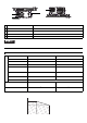
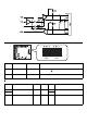
1 10
1 10
SW4 SW1 SW2 SW3
OFF
ON
ON
OFF
Bottom face of the control box
(CI)RI
5V