
User Manual

4
• When attaching peripheral units to the PL, be sure the PL’s power cord is
disconnected from the main power supply.
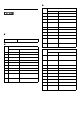
General Specificati on s
Electr ical Specifications
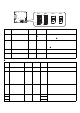
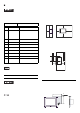
Name Description
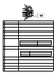
T Fan cover System fan inside
U System fan A fan for cooling the PL unit.
V Power connector —
W Power switch AC type only.
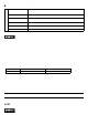
Power Supply
DC type AC type
Input Voltage DC24V AC100 to 240V
Rated Voltage DC19.2 to 28.8V AC85 to 264V
Rated Frequency — 50/60Hz
Allowable Frequency
Range
— 47 to 63Hz
Allowable Voltage
Drop
5ms or less
1 cycle or less (Voltage drop
interval must be 1s or more.)
*1
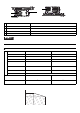
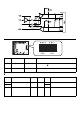
*1 When the tot al of the exp ansion sl ot pow er and the external load pow er exceeds 1 5W, the length of
the allowable voltage drop will be 20ms or less. For details, refer to the graphs below.
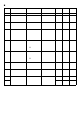
Power Consumption 145W or less 145VA or less
In-Rush Current 40A or less
Voltage Endurance
AC1000V 20mA for 1 minute
(
between charging and FG terminals
)
AC1500V 20mA for 1 minute
(
between charging and FG terminals
)
Insulation Resistance
DC500V 10MΩ (min.)
(
between charging and FG terminals
)
DC500V 10MΩ (min.)
(
between charging and FG terminals
)
Bottom
(2 slot type)
T
V
To p
(2 slot type)
W
U
J
Allowable Range
(ms)
20
14
35 40 (W)
0
15