
User Manual

3
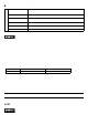
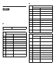
Name Description
F DVI-I interface (DVI-I) For analog RGB output only.
*1
*1 DVI monitor cannot be connected.
G
Ethernet interface
(LAN1)
10BASE-T/100BASE-TX/1000BASE-T Auto Chan geo ver . Th is
interface uses an RJ- 45 type modula r jack conne ctor (8 pin s).
H
Ethernet interface
(LAN2)
10BASE-T/100BASE-TX Auto Chan geover. This interface uses
an RJ-45 type modular ja ck conne ctor (8 pins).
I Expansion slot For expansion board (PCI). 2 slot s or 4 slots.
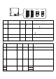
J Expansion slot cover
Expansion slot cover is removed when mounting expansion
board and DIM module.
K HDD slot
For serial ATA HDD/SSD unit. HDD slot 0 and then HDD slot
1 from the left.
L
USB interfac e
(USB1/2/3/4)
4 ports. USB2.0 comp atible . Type-A connector is used.
M
Speaker output
interface (SPK)
Mini pin jack connector
N HDD status lamp
For HDD slot 0 and for HDD slot 1 from left to right.
O
Serial interface
(COM1)
D-Sub 9-pin plug type. RS-232C, RS-422, RS-485
Changeover. CI (RI)/+5V Changeover.
P
Serial interface
(COM2)
D-Sub 9-pin plug type. RS-232C. CI (RI)/+5V Changeover.
Q
Serial interface
(COM3/COM4)
D-Sub 9-pin plug type. RS-232C. COM3 and then COM4
from the top.
R RAS interface (RAS) D-Sub 9 pin socket type.
S
CF card interface
(CF CARD)
IDE-type connection
*2
CF card (Type I/II) is available.
*2 Since an IDE-type connection is used, the unit is not hot-swappable. When insert ing/removing the
CF card, be sure that power is turned OFF.
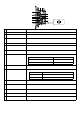
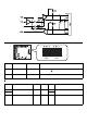
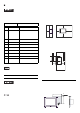
Right side
(2 slot type)
F
IJ
L
M
O
P
S
R
N
B
N
A
K
Q
H
G
D
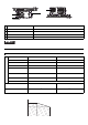
Power supply voltage DC5V±5%
Output current 500mA (Max.)
Maximum communication distance
5m
LED Indicates
Green (lit)
HDD/SSD mounted (Normal operation)
Not lit No HDD/SSD mounted