
User Manual

12
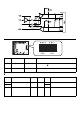
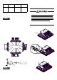
(4) Slide the control box in direction shown
by the arrow.
(5) Lift the control box and remove the front
module tabs from the slot on the installa-
tion fasteners for the control box. Then
remove the control box.
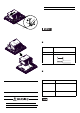
2. Installing the front module and the
control box
Install the control bo x to th e front mod ule
in the reverse order of the uninstallation
steps. The necessary torque is 0.5N•m to
0.6N•m in every step.
Wiring
• To avoid an electric shock, prior to con-
necting the PL unit’s power cord terminals
to the power terminal block, confirm that
the PL unit’s power supply is completely
turned OFF, via a breaker , or similar unit.
• Any other power level can damage
both the PL and the power supply.
• Since DC type has no power ON/OFF
switch, be sure to attach a breaker-
type switch to its power cord.
• When the FG terminal is connected, be
sure the wire is grounded.
1. Wiring the power supply cable
• When the FG terminal is connected, be
sure the wire is grounded. Not
grounding the PL unit will result in
excessive noise. Use your country’s
applicable standard for grounding.
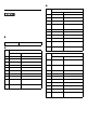
Power Cord Specifications
Use copper conductors only.
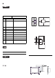
Wiring
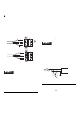
When connecting the power code, use the
following items when performing wiring.
(Items are made by Phoenix Contact.)
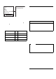
• Accompanying power supply connector is
the following items.
AC type :
Use the bridge
position as a guide.
Power Cord
Diameter
0.75 to 2.5mm
2
(18 - 12 AWG)
Conductor Type
Simple or Stranded Wire
*1
*1 If the Conductor’s end (individual) wires are not
twisted correctly , the end wires may either short
against each o ther , or agains t an electrode .
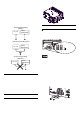
Conductor
Length
Recommended
Driver
SZS 0.6x3.5 (1205053)
Recommended
Pin Terminals
AI 0.75-10GY(3201288)
AI 1-10RD (3200182)
AI 1.5-10BK (3200195)
AI 2.5-12BU (3200962)
Recommended
Pin Terminal
Crimp Tool
CRIMPFOX ZA3
(1201882)
10mm [0.39in]