
User Manual

10
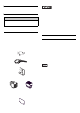
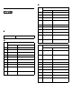
RAS Interface
• Be sure to use only the rated voltage
level when using pin #1 (+12V) for
external power outpu t. Fail ure to do so
can lead to a unit malfunction or acci-
dent.
• For the circuit diagram, refer to “PL3000
Series Reference Manual”.
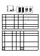
Installations
• Before installing the PL unit on the
panel, detach the control box from the
front module to configure the settings
of the internal switches.
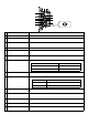
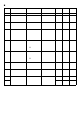
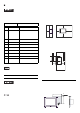
1. Installation Requirements
• For easier maintenance, operation, and
improved ventilation, be sure to install the
PL at least 50mm [1.97 in.] away from
adjacent structures and other equipment.
For the face to which the cable is con-
nected, however, a space of 120 mm [4.72
in.] or more is necessary for cable curve.
• Be sure that the surrounding air temperature
and the ambient humidity are within their
specified ranges.
When installing the PL on the panel of a
cabinet or enclosure, “Surrounding air tem-
perature” indicates both the panel face and
cabinet or enclosure’ s internal temperature.
• Be sure that heat from surrounding equip-
ment does not cause the PL to exceed its
standard operating temperature.
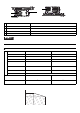
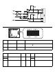
2. PL Installation
(1) Create a Panel Cut using the dimensions
in the following table. Also, determine
the panel thickness according to the panel
thickness range with due consideration of
panel strength.
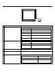
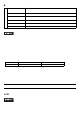
Interfit Bracket #4-40(UNC)
Pin #
Signal Name
Description
1 +12V
Output Current:
100mA or less
Output Voltage:
12V
±
5%
2 DOUT0(+) Data out 0(+)
3 DOUT1(+) Data out 1(+)
4 DIN0(+) Dat a in 0(+)
5 DIN1(+) Data in 1(+)
*1
*1 Can be used as reset input.
6 GND Ground
7 DOUT0(-) Data out 0(- )
8 DOUT1(-) Data out 1(-)
9DINCOM
Data in ground
common
SEE
Installation/uninstallation of the
front module and the control
box, Internal Switches
Unit:mm[in.]
120
[4.72]
50
[1.97]
50
[1.97]
50
[1.97]
50
[1.97]
50
[1.97]
50
[1.97]
Panel face
Cabinet
interior
30
[1.18]
30
[1.18]
unit:mm[in.]
50
[1.97]
PL
X
Unit:mm[in.]
Y
r
≤
3[0.12]
Panel
thickness