
User guide


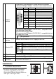


7
• The power for the analog module
should be supplied separately from the
HTB.
Turn the analog module on before
turning the HTB on. Wait at least 30
seconds after power-off to restart the
external power-supply or it may not
operate properly.
• Be sure the analog OUT lines are
placed in a separate duct from high-
frequency, live lines such as high-
voltage, high-power lines, inverters, etc.
0 I0
1 I1
2 I2
3 I3
COM0
NC
Q0 0
Q1 1
Q2 2
Q3 3
COM1
<EXM-DMM8DRT>
(1) Source input
(2) Sink input
(1)
(2)
-
+
+
-
+
-
+
-
IN0
IN1
+
-
NC
+
-
Analog voltage/
current output
device
DC24V
DC
24V
<EXM-AMI2HT>
Analog voltage/
current output
device
-
+
+
-
+
-
OUT
+
-
DC24V
DC
24V
<EXM-AMO1HT>
Analog voltage/
current input
device
-
+
+
-
+
-
+
-
+
-
OUT
IN0
+
-
NC
+
-
IN1
NC
+
-
A
B’
B
A
B’
B
*1
*1 The (-) poles of inputs IN0 and IN1 are con-
nected internally.
DC24V
DC
24V
<EXM-AMM3HT>
Analog voltage/
current output
device
Analog voltage/
current output
device
Analog voltage/
current input
device
-
+
+
-
B’
B
+
-
A
+
-
OUT
IN0
+
-
NC
+
-
IN1
NC
+
-
A
B’
B
A
B’
B
2-wire cabling for Temperature Probes :
RTD
DC24V
DC
24V
Thermocouple
(K, J, T)
Shield
<EXM-ALM3LT>
Analog voltage/
current input
device
-
+
+
-
B’
B
+
-
A
+
-
OUT
IN0
+
-
NC
+
-
IN1
NC
+
-
A
B’
B
A
B’
B
3-wire cabling for Temperature Probes :
RTD
DC24V
DC
24V
T
hermocouple
(K, J, T)
Shield
<EXM-ALM3LT>
Analog voltage/
current input
device