
User guide


5
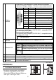
1. Arrangement of the HTB’s power cable and the I/O cables
Power Cord Specifications
Power Cord
1 mm
2
to 1.5mm
2
(AWG 18 and AWG
16). Use the shortest wire length
possible. The grounding wire should
be 1.50 mm
2
(AWG 16).
I/O cables
0.20 mm
2
to 1.31 mm
2
, (AWG 24 to
AWG 16).
(accepts up to two wires fitted with
cable ends or tags)
2. EX module connecting diagram
• Please install an applicable fuse to prevent an overload in the circuit, if necessary.
Power supply
section Ø 3.5 mm [0.14 in.]
C
N·m 0.6
In/Output terminal
connector
Ø 2.5 mm [0.10 in.]
N·m 0.4
(1) Source input
(2) Sink input
(1)
(2)
(1)
(2)
<EXM-DDI16DT>
(1) Source input
(2) Sink input
*1 The terminals are
connected together
internally.
*1
*1
0
1
2
3
4
5
6
7
COM
COM
0
1
2
3
4
5
6
7
COM
COM
8
9
10
11
12
13
14
15
COM
COM
<EXM-DDI8DT>