
User guide


3
Installations
1. Installation Requirements
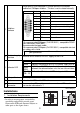
• In order to ensure proper serviceability,
operability and airflow, provide space
between the HTB and structural objects or
other parts as the figure shows.
C
Field bus
interface
A 9-pin plug D-SUB connector is used to connect the interface
module to a CANopen field bus. This bus is not insulated internally.
Recommended cable connector:
CiA-recommended CANopen (CiA DR-303-1) -compatible DSUB
9-pin connector (DIN41652) .
Recommended network cable:
CiA-recommended CANopen (CiA DR-303-1) -compatible twisted
pair cables with shield.
Note: Please use your own cables or cable connectors with
your guarantee.
D
Electrical supply
Interface
Terminal for an external 24 VDC supply of the HTB.
E Indicator LED
F
In/Output Terminals
Input/Output terminals.
G Hook A hook to fix HTB on the DIN rail.
H
Extension
Connector
For connecting EX modules; maximum number of EX modules
that can be connected is 7.
Contacts Signal Description
1- -
2 CAN_L CAN-L bus line
3 CAN_GND CAN Ground
4- -
5- -
6GND
Ground(Common with CAN_GND)
7 CAN_H CAN-H bus line
8- -
9- -
Shell FG Frame Ground
LED
Status
PWR
Indicates the presence of a 24 VDC power supply to HTB.
RUN
ERR
2 (RUN) and 3 (ERR) show the data exchange status
between the communication units that can transmit data.
I0 - I11
Q0 - Q7
Reflect the I/O status of HTB’s integrated I/O.
20 [0.79]
80 [3.15]
Unit : mm [in.]
20 [0.79]
20 [0.79]
40
[1.57]
40
[1.57]
20 [0.79]