
Manual


14
5. Input/Output Signal Line Cautions
• All GP Input and Output signal lines
must be separated from all operating
circuit (power) cables.
• If this is not possible, use a shielded
cable and ground the shield.
Securing the USB cable con-
nection
• When using USB Host Interface in
Hazardous Locations, please fix the
USB cable with the USB Holder. If it’s
not fixed so that the connector on the
GP’s side and the PLC’s side cannot
come out, the USB Host Interface can-
not be used in the Hazardous Loca-
tions.
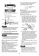
Attaching the USB Holder
(1) Before starting the procedure, orient
the two tabs on both sides of the USB
Holder in the direction of the arrows in
the figure and remove the USB Cover.
(2) Attach the USB holder to the USB
Host Interface part of the main unit.
Hook the lower pick of the USB holder
to the attachment hole of the main
unit and then insert the upper pick as
shown below to fix the USB holder.
(3) Insert the USB cable into the USB
Host Interface.
(4) Attach the USB cover to fix the USB
cable. Insert the USB cover into the
tab of the USB holder.
In case of installing the second USB
cable, repeat the step 3, 4.
GP unit
Other
Equipment
Common Grounding (OK)
GP unit
Other
Equipment
Common Grounding
(Not OK)
Tabs
GP-3500/3600 Series GP-3700 Series
GP-3500/3600 Series GP-3700 Series
USB Cable
USB Holder
Tab
USB Cover
GP-3500/3600 Series GP-3700 Series
Tab