
Manual


12
(4) Reattach the Terminal Strip's clear
plastic cover.
2. Wiring the DC Type Power Cord
Power Cord Specifications
Use copper conductors only.
Power Connector (Plug) Specifications
• The power connector (plug) is CA5-
DCCNL-01 made by Pro-face or
GMVSTBW2,5/3-STF-7,62 made by
Phoenix Contact.
When connecting the Power Cord, use the
following items when performing wiring.
(Items are made by Phoenix Contact.)
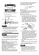
Connecting the GP Power Cord
(1) Confirm that the GP unit’s Power
Cord is unplugged from the power
supply.
(2) Remove the power connector (plug)
from the GP unit.
(3) Loosen the three screws in the
center of the Power Connector.
(4) Strip the power cord, twist the
conductor’s wire ends, insert them
into the pin terminal and crimp the
terminal. Attach the terminal to the
power connector.
(5) Fix it with screws.
• Use a flat-blade screwdriver (Size 0.6
X 3.5) to tighten the terminal screws.
The torque required to tighten these
screws is 0.5 to 0.6 N•m [5-7 Lb•In.].
• Do not solder the cable connection.
Doing so may damage the unit due to
abnormal heat or cause a fire.
Power Cord
Diameter
0.75 to 2.5 mm
2
(18 - 12 AWG)
Conductor
Type
Simple or Stranded Wire
*1
*1 If the Conductor’s end (individual) wires are not
twisted correctly, the end wires may either short
against each other, or against an electrode.
Conductor
Length
+ 24V
-
0V
FG
Grounding
Terminal
connected
to the GP
chassis
DON’T
CONNECT
FG (Frame Ground) Terminal
7 mm
[0.28 in]
Power Cord
Insertion holes
FG
+
-
Recomended
Driver
SZF 1-0.6x3.5
(1204517)
Recomended
Pin Terminals
AI 0.75-8GY (3200519)
AI 1-8RD (3200030)
AI 1.5-8BK (3200043)
AI 2.5-8BU (3200522)
Recomended
Pin Terminal
Crimp Tool
CRIMPFOX ZA 3
(1201882)