
User Manual


Chapter 2 Specifications
2-9
2.3.2 Ethernet Interface
Ethernet (IEEE802.3u, 10BASE-T/100BASE-TX) with modular jack connector (RJ-45)
2.3.3 DC24V Interface
*1 Select AWG16 cable to use out of two green cables.
• If isolation is required, use the RS-232C isolation unit (CA3-ISO232-01) by Pro-face, and the
following recommended equipment.
Recommended Intermediate Connector XM2A-0901 <made by OMRON Corp.>
Recommended Fastener 1 XM2Z-0003 <made by OMRON Corp.>
Recommended Cable Cover XM2S-0913 <made by OMRON Corp.>
Cable Color Signal Name Direction Description
Blue TX + Output Ethernet Send (+)
White TX - Output Ethernet Send (-)
Brown RX + Input Ethernet Receive (+)
Gray RX - Input Ethernet Receive (-)
To avoid an electric shock, prior to connecting the GP unit's power cord terminals to the
power terminal block, confirm that the GP unit's power supply is completely turned OFF, via
a breaker, or similar unit.
Supplying a power voltage other than that specified will damage the power source and the
GP unit.
Since there is no power switch on the GP unit, be sure to attach a breaker-type switch to its
power cord.
When the FG terminal is connected, be sure the wire is grounded.
Cable Color Signal Name Direction Description
Red DC24V Input Power Input DC24V
Black 0V Input Power Input 0 V
Green FG
*1
- Frame Ground (Common with SG)
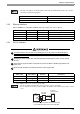
• Be sure to twist Power Input wires from a part close to the power supply.
• It's recommended to use the provided common mode filter on the direct-connect cable to reduce
noise.
External
power supply
24 VDC
GP
24 VDC
Common
field filter
3
0 V
24 VDC
0 V
4
1
2
FGFG
■ The black square indicates the connection point
for the dedicated cable and common field filter.