
User Manual


Chapter 1 Overview
1-13
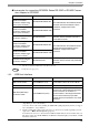
1.3 Part Names and Functions
A: Status LED (POWER)
This LED indicates the GP's status, e.g. power
input, firmware RUN status or backlight condition.
B: Operation LED (O.P.)
C: Operation Switch
When this switch is enabled, the GP unit can
accept touch panel input and function key input,
only while this switch is being pressed.
D: Function Switches (11 switches)
The switch functions are set up with the screen
design software. For details, refer to the GP-Pro
EX Reference Manual.
E: Emergency Switch
F: Key Switch
Turning the key turns ON/OFF the GP unit power
supply.
G: CF Card Cover
The CF Card I/F, USB I/F, Dip Switches and LAN
Status LED are located in the CF Card Cover open.
Color Indicator Operation Mode
Green ON
OFFLINE
In operation
Red ON When power is turned on.
Orange
ON
Backlight burnout
or GP malfunction
*1
*1 When backlight replacement or repair of the
GP is required, please contact your local GP
distributor.
Flashing During software startup
OFF Power is OFF.
LED GP Status
Green
Indicates the Operation Switch is
ON.
Not Lit
Indicates the Operation Switch is
OFF.
• During operation of the GP unit, keep the
CF Card cover closed. Operating the GP
with the cover left open removes the
dust-proof and droplet-proof protection.
Doing so could cause a unit malfunction.
Front
E
A
B
C
D
Top
G
CF Card Cover Open
F
G
H
I
J, K