
Manual


4
External Interfaces
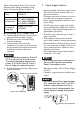
• This ST unit’s serial interface is not isolated.When the host (PLC) unit is also not iso-
lated, and to reduce the risk of damaging the RS232C/RS422/RS485 circuit, be sure
to connect pin #5 SG (Signal Ground) terminal.
• Similarly shaped connectors are used for COM1 and COM2 of the ST. Therefore, be
sure to connect the correct connectors. Communication is not available unless the
connectors are connected correctly.
• When isolation is necessary, you can use the RS232C isolation unit (CA3-ISO232-01) on
COM1.
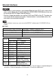
COM1
Recommended Cable Connector XM2D-0901 <made by OMRON Corp.>
Recommended Jack Screw XM2Z-0073 <made by OMRON Corp.>
Recommended Cable Cover XM2S-0913 <made by OMRON Corp.>
Interfit Bracket #4-40 inch screws are used.
Pin #
RS232C
Signal Name Meaning
1 CD Carrier Detect
2 RD(RXD) Receive Data
3 SD(TXD) Send Data
4 ER(DTR) Data Terminal Ready
5 SG Signal Ground
6 DR(DSR) Data Set Ready
7 RS(RTS) Request to Send
8 CS(CTS) Clear to Send
9CI(RI)/VCC
Called status display/
+5V±5% Output 0.25A
*1
*1 The RI/VCC selection for Pin #9 is switched via software. The VCC output is not protected against
overcurrent. To prevent damage or unit malfunctions, use only the rated current.
Shell FG
Frame Ground
(Common with SG)