
Instruction Manual


-5-
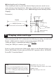
The RS-485/RS-422
type
The communication method is switched with a change switch.
Dsub 9-pin socket connector's pin assignments are as follows.
Unit’s Connector : XM3B-0942-132L <made by OMRON>
Recommended Connector : XM2A-0901 <made by OMRON>
Recommended Cover : XM2S-0913 <made by OMRON>
Jack Screw : XM2Z-0073 <made by OMRON>
Stacking Metal Fittings require #4-40 inch screw.
*1 The VCC output for Pin #6 is not protected against overcurrent. To prevent damage or unit mal-
functions, use only the rated current.
RS422
RS485
.3.2 RS-485 Isolation Unit
Signal
Name
Direction Meaning
1TRMRX-
Termination
(Receive side:100Ω)
2--
3 Input/Output Receive/Send DataA(+)
4 NC - No connection
5 SG - Signal Ground
6VCC-
+5V±5% output 0.05A
*1
7--
8 Input/Output Receive/Send DataB(-)
9TRMTX-
Termination
(Send side:100Ω)
Shell FG - Frame Ground
Pin Arrangement Pin #
RS-485
RDB/SDB
RDA/SDA
RS-485
5
1
9
6
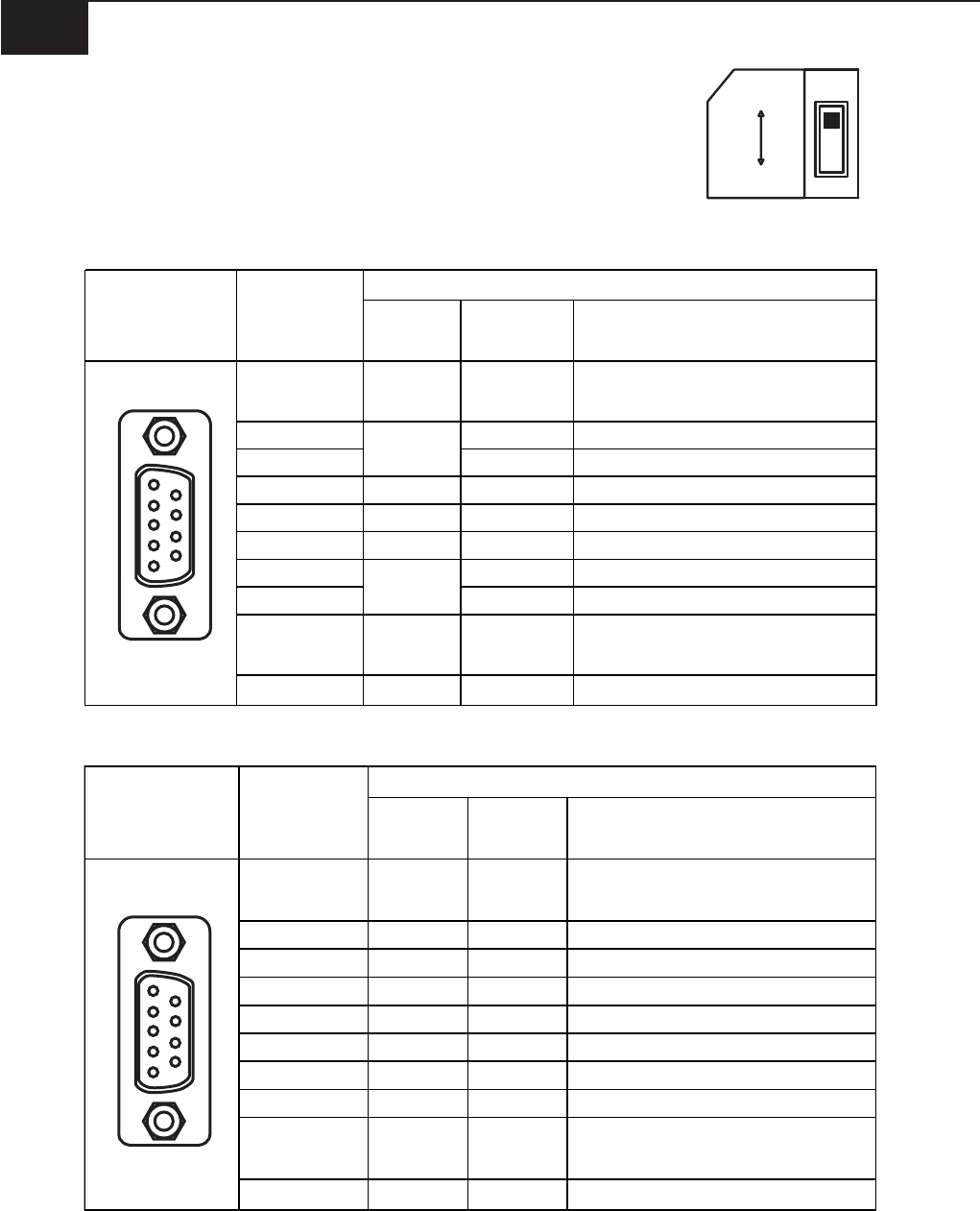
RS-422
Signal
Name
Direction Meaning
1 TRMRX -
Termination
(Receive side:100Ω)
2 RDA Input Receive DataA(+)
3 SDA Output Send DataA(+)
4 NC - No connection
5 SG - Signal Ground
6VCC-
+5V±5% output 0.05A
*1
7 RDB Input Receive DataB(-)
8 SDB Output Send DataB(-)
9TRMTX-
Termination
(Send side:100Ω)
Shell FG - Frame Ground
Pin Arrangement Pin #
RS-422
5
1
9
6