
Instruction Manual


-4-
The RS-232C/RS-422 type
The communication method is switched with this unit’s DIP switch.
• For Display side settings please refer to “5 Display side settings”.
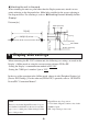
Dsub 9-pin plug connector’s pin assignments are as follows.
Unit’s Connector : XM2C-0942-132L <made by OMRON>
Recommended Connector : XM2D-0901 <made by OMRON>
Recommended Cover : XM2S-0913 <made by OMRON>
Jack Screw : XM2Z-0073 <made by OMRON>
Stacking Metal Fittings require #4-40 inch screw.
• This unit does not correspond to RS-422/485 (2 wire) communication.
• This unit does not correspond to Serial Multilink communication.
Signal
Name
Direction Meaning
1 CD Input Carrier Detect
2 RD(RXD) Input Receive Data
3 SD(TXD) Output Send Data
4 ER(DTR) Output Data Terminal Ready
5 SG - Signal Ground
6 DR(DSR) Input Data Set Ready
7 RS(RTS) Output Request to Send
8 CS(CTS) Input Clear to Send
9 NC - No connection
Shell FG - Frame Ground
Pin Arrangement Pin #
RS-232C
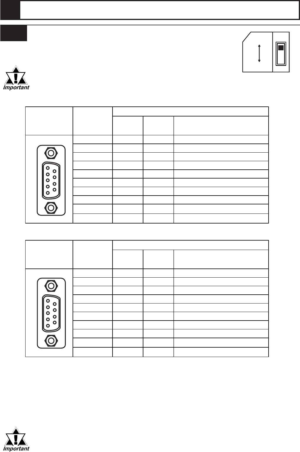
Signal
Name
Direction Meaning
1 RDA Input Receive DataA(+)
2 RDB Input Receive DataB(-)
3 SDA Output Send DataA(+)
4 ERA Output Data Terminal ReadyA(+)
5 SG - Signal Ground
6 CSB Input Send PossibleB(-)
7 SDB Output Send Data B(-)
8 CSA Input Send PossibleA(+)
9 ERB Output Data Terminal ReadyB(-)
Shell FG - Frame Ground
Pin Arrangement Pin #
RS-422
RS-232C
RS-422
3.1 RS-232C Isolation Unit
3 Serial Interface Specifications
5
1
9
6
5
1
9
6
RS232C
RS422