
User Manual


2
DIO Interface (Connector)
• When preparing the cable to connect the wiring, check the pin numbers inscribed on
the DIO Connector.
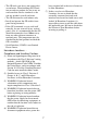
Input Specifications
Input Circuit
Applicable connector 1-1871940-6 <Tyco Electronics AMP.>
Pin Arrangement Pin No. Signal Name Pin No. Signal Name
A1 0V B1 +24V
A2 OUT1 B2 OUT0
A3 NC B3 COM
A4 IN5 B4 IN4
A5 IN3 B5 IN2
A6 IN1 B6 IN0
Rated Voltage
DC 24V
Maximum Allowable Voltage
DC 28.8V
Input Method Source/Sink Input
Rated Current
5.7 mA (DC24V)
Input Resistance
4.2 kΩ
Operation
Range
ON Voltage DC 15V or more
OFF Voltage DC 5V or less
Input Delay
Time
OFF to ON
1.5 ms or less
ON to OFF
1.5 ms or less
Common Lines 1
Common Design 6 points/1 common line
External Connection 12-pin connector (used with Output section)
Input Points 6
Input Signal Display No LED indicators
Status Display None
Isolation Method Photocoupler Isolation
External Power Supply For Signal: DC 24V
(Cable connection side)
A1
B1
B6
A6
DC 24V
External Power
Internal Circuit
Internal Circuit
COM B3
+
-
IN5 A4
IN4 B4
IN3 A5
IN2 B5
IN1 A6
IN0 B6
-
+
*1
*1 Dotted line shows
connection to sink
output type.