
Owner's manual


5
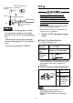
COM2
Recommended Cable
Connector
XM2D-0901 <made by OMRON Corp.>
(AST3201-A1-D24 only)
XM2A-0901 <made by OMRON Corp.>
(AST3211-A1-D24 only)
Recommended Jack Screw XM2Z-0073 <made by OMRON Corp.>
Recommended Cable Cover XM2S-0913 <made by OMRON Corp.>
Interfit Bracket #4-40 inch screws are used.
Pin #
RS422/RS485
*1
(AST3201-A1-D24 only)
*1 RS485 is compliant with AST-3201A units with revision code “C” or later.
Revision (page 11)
RS485 (MPI only)
(AST3211-A1-D24 only)
Signal Name Meaning Signal Name Meaning
1 RDA Receive Data A(+) NC
⎯⎯
2 RDB Receive Data B(-) NC
⎯⎯
3 SDA Send Data A(+) LINE(+)
Line(+)
4 ERA Data Terminal Ready A(+) RS(RTS)
Request to Send
5 SG Signal Ground SG
Signal Ground
*2
*2 In COM2 on the AST3211-A1-D24, the SG and FG terminals are isolated.
6 CSB Clear to Send B(-) 5V
5V External Output
*3*4
*3 The 5V output for Pin #6 is not protected against overcurrent. To prevent damage or unit
malfunctions, use only the rated current.
*4 When providing power via the Siemens Co.'s Profibus connector, power cannot be connected to the
Device/PLC.
7 SDB Send Data B(-) NC
⎯⎯
8 CSA Clear to Send A(+) LINE(-)
Line(-)
9 ERB Data Terminal Ready B(-) NC
⎯⎯
Shell FG
Frame Ground
(Common with SG)
FG Frame Ground
*2
SEE