
Owner manual


12
4. Input/Output Signal Line Cautions
• All GP Input and Output signal lines
must be separated from all operating
circuit (power) cables.
• If this is not possible, use a shielded
cable and ground the shield.
Securing the USB cable con-
nection
• When using USB Host Interface in
Hazardous Locations, please fix the
USB cable with the USB Holder. If it’s
not fixed so that the connector on the
GP’s side and the PLC’s side cannot
come out, the USB Host Interface can-
not be used in the Hazardous Loca-
tions.
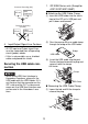
1. GP-3300 Series units (Except for
AGP-3310T/AGP-3360T)
Attaching the USB Cable Clamp
(1) Insert the USB holder into the slot in
front of the GP unit’s USB port and
pull it down and forward.
(2)
Pass the band of the USB cable clamp
through the bridge of the USB holder.
(3) Insert the USB cable into the port.
Fasten the band around the plug and
secure it with the clamp.
Removing the USB Cable Clamp
(1) Lower the tab and lift the clamp to
release the plug.
GP unit
Other
Equipment
Common Grounding (OK)
GP unit
Other
Equipment
Common Grounding
(Not OK)
1
2
USB Holder
Bridge
USB Holder
Clamp
USB Cable
Tab
Clamp