
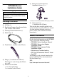
User guide


8
DC24 V Interface
y To avoid an electric shock, prior to connecting the GP unit’s power cord terminals to
the power terminal block, confirm that the GP unit’s power supply is completely
turned OFF, via a breaker, or similar unit.
y Supplying a power voltage other than that specified will damage the power source
and the GP unit.
y Since there is no power switch on the GP unit, be sure to attach a breaker switch to
the power cord.
y When the FG terminal is connected, be sure the wire is grounded.
• Be sure to twist Power Input wires from a part close to the power supply.
• It's recommended to use the provided common mode filter on the direct-connect cable to
reduce noise.
Power Supply Cautions
• Input and Output signal lines must be separated from the power control cables for operational
circuits.
• To improve the noise resistance, be sure to twist the ends of the power cord wires before
connecting them to the power supply.
• The GP unit’s power supply cord should not be bundled with or kept close to main circuit
lines (high voltage, high current), or input/output signal lines.
• To reduce noise, make the power cord as short as possible.
• If the supplied voltage exceeds the GP unit’s range, connect a voltage transformer.
• Between the line and the ground, be sure to use a low noise power supply. If there is an excess
amount of noise, connect a noise reducing transformer.
• The temperature rating of field installed conductors: 60°C only.
• DC 24V input unit must be used with a Class 2 power supply.
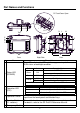
Cable Color Signal Name Direction Description
Red DC24 V Input Power Input DC24 V
Black 0 V Input Power Input 0 V
Green FG
*1
*1 Select AWG16 cable to use out of two green cables.
⎯
Frame Ground (Common with SG)
External
power supply
24 VDC
GP
24 VDC
Common
field filter
3
0 V
24 VDC
0 V
4
1
2
FGFG
■ The black square indicates the connection point
for the dedicated cable and common field filter.