
User guide


2
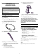
Part Names and Functions
Name Description
A
Status LED
(POWER)
This LED indicates the GP’s status, e.g. power input, firmware
RUN status or backlight condition.
B
Operation LED
(O.P.)
C Operation Switch
When this switch is enabled and pressed, the GP unit can accept
input from the touch panel and function keys.
D
Function Switches
(11 switches)
The switch functions are set up with the screen design software.
For details, refer to the GP-Pro EX Reference Manual.
E Emergency Switch ⎯
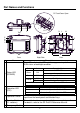
Front
L
H
I
GM
Q
G
G
F
J, K
O
N
P
F
O
T
E
A
B
C
D
R
Top
RearRight Side
CF Card Cover Open
S
Color Indicator Operation Mode
Green ON
OFFLINE
In operation
Red ON
When power is turned on.
Orange
ON Backlight burnout
Flashing During software startup
Not Lit Power is OFF.
LED GP Status
Green Indicates the Operation Switch is ON.
Not Lit
Indicates the Operation Switch is OFF.