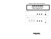
MANUALE UTENTE / INSTRUCTION MANUAL AUP120/240/480R Amplificatore di potenza Power Amplifier Unit
1. PRECAUZIONI D’USO AVVERTENZA:Per ridurre il rischio di folgorazione, non rimuovere il coperchio (o il pannello posteriore). All’interno non sono contenute parti riparabili dall’utente; affidare la riparazione a personale qualificato. ATTENZIONE: Per ridurre il rischio d’incendio o di folgorazione, non esporre questo apparecchio alla pioggia o all’umidità.
Le note precedute dal simbolo contengono importanti informazioni sulla sicurezza: leggerle con particolare attenzione. ISTRUZIONI DI SICUREZZA IN DETTAGLIO. Acqua ed umidità: L’apparecchio non deve essere utilizzato in prossimità di acqua (per es. vicino a vasche da bagno, lavelli da cucina, in prossimità di piscine ecc.). Ventilazione: L’apparecchio deve essere posto in modo tale che la sua collocazione o posizione non interferisca con l’adeguata ventilazione.
Ingresso di liquidi o oggetti: Si deve prestare attenzione che non cadano oggetti e non si versino liquidi nel corpo dell’apparecchio attraverso le griglie. Uso sicuro della linea d’alimentazione: • Quando si scollega l’apparato alla rete tenere saldamente sia la spina che la presa.
• Avvitare completamente i terminali a vite degli altoparlanti per garantire la sicurezza dei contatti. • Per ragioni di sicurezza, non annullare il collegamento a massa della spina. Il collegamento a massa è necessario per salvaguardare la sicurezza dell’operatore Utilizzare unicamente i connettori e gi accessori specificati dal produttore.
Grazie per aver scelto un prodotto Proel e della fiducia riposta nel nostro marchio, sinonimo di professionalità, accuratezza, elevata qualità ed affidabilità. Tutti i nostri prodotti sono conformi alle normative CE per utilizzazione continua in impianti di diffusione sonora. 2. Descrizione L’ AUP120/240/480R è stato specificatamente progettato per la trasmissione di annunci e/o programmi musicali in tutti i sistemi PA. Esso presenta: • Un ingresso/uscita bilanciato su connettore XLR.
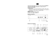
(3) Led overload Il led si illumina quando il dispositivo entra in funzione di autoprotezione. (4) Interruttore d’accensione (5) Controlli di tono I controlli di tono svolgono un intervento di +/- 10 dB nello spettro delle frequenze dei bassi ed acuti, permettendo di effettuare una corretta equalizzazione del segnale riprodotto. (6) Fusibile di protezione Protegge il dispositivo da eventuali sbalzi di tensione della rete di alimentazione e può essere sostituito.
(16)Controllo di guadagno per ingresso base microfonica BM100A. (17)Controllo di guadagno per ingresso centrale telefonica. (18)Selettore Ground-lift (19)Filtro PA-HF. Permette l’inserzione di un filtro passa-alto con taglio a 400Hz -3dB. Questo filtro si rende utile in caso di pilotaggio di soli altoparlanti a tromba oppure di sola diffusione di segnale vocale. (20)Messa a terra (21)Presa cavo alimentazione di rete (22)Alette di fissaggio su RACK 19”. PANNELLO FRONTALE fig.1 PANNELLO POSTERIORE fig.
4. INSTALLAZIONE Note • Per consentire il normale raffreddamento dello stadio finale, posizionare l’amplificatore in un ambiente ben ventilato e al riparo da fonti di calore, evitare l’esposizione diretta ai raggi solari. • Non posizionare l’amplificatore in posti soggetti a elevate vibrazioni o particolarmente esposti all’umidità e alla polvere.
Nota Se l’alimentazione in continua è fornita mediante l’utilizzo di una batteria informiamo l’utente che il dispositivo non è in grado di provvedere all’eventuale ricarica della stessa. 7. CONNESSIONE INGRESSO BILANCIATO / SBILANCIATO Per la connessione bilanciata e sbilanciata fare riferimento ai seguenti schemi. Attenzione Per prevenire il rischio di contatto con scariche elettriche non toccare mai le uscite dell’amplificatore quando esso è in funzione.
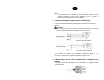
9. CONNESSIONE SEGNALE AUDIO DA CENTRALE TELEFONICA Collegare il terminale di uscita della centrale telefonica alla morsettiera TEL INPUT (fig.2 rif.15). In base alla tipologia dell’uscita audio, utilizzare la connessione più adatta, fare riferimento al manuale d’istruzioni della centrale telefonica. Connessione Bilanciata Connessione Sbilanciata 10. CONNESSIONE SEGNALE AUDIO SU CONNETTORI MUSIC INPUT / MUSIC OUTPUT A tale scopo riferirsi ai seguenti schemi di connessione.
BILANCIATO 11. LINEA A IMPEDENZA COSTANTE Per ottenere una linea a impedenza costante (8Ω) collegare i 2 terminali rispettivamente ai morsetti COM e 8Ω (fig.2 rif. 10). • Al fine di garantire il massimo rendimento, l’impedenza totale degli altoparlanti collegati alla linea, deve essere uguale all’impedenza dell’uscita dell’amplificatore. • La somma della potenza degli altoparlanti non deve essere inferiore alla potenza di uscita dell’amplificatore.
. SETTAGGIO DEL MODO DI FUNZIONAMENTO DELL’AMPLIFICATORE DI POTENZA L’amplificatore possiede tre differenti modi di funzionamento : • STAND ALONE: L’amplificatore funziona in maniera indipendente • MASTER: L’amplificatore, mediante i controlli VOLUME, TREBLE, e BASS, controlla oltre che alla propria uscita in potenza anche il segnale MUSIC OUTPUT. In questa configurazione esso può controllare più amplificatori configurati come SLAVE.
Togliere il coperchio dell’amplificatore ed individuare, sulla scheda dei potenziometri VOLUME, TREBLE e BASS dal lato rame, i jumper SW1 e SW2. Posizionare i jumper SW1 e SW2 scegliendo una tra le seguenti configurazioni: Nota: L’apparecchio di fabbrica è configurato come STAND ALONE.
Caratteristiche Tecniche MODEL AUP120R Output Power RMS AUP240R AUP480R 120/180MAX 240/360MAX 480/680MAX 100mV-500mV1V/47Kohm select. Variable gain 600ohms Variable gain - with priority contact 50 -20KHz 100mV-500mV1V/47Kohm select. Variable gain 600ohms Variable gain - with priority contact 50 -20KHz 100mV-500mV1V/47Kohm select.
1. IMPORTANT SAFETY INSTRUCTIONS CAUTION: To reduce the risk of electric shock do not remove cover (or back panel). No user serviceable parts inside. Refer servicing to qualified personnel only. WARNING: To reduce the risk of fire or electric shock, do not expose this apparatus to rain or moisture. This symbol is intended to alert the user of the presence of uninsulated dangerous voltage within the product enclosure that may be of sufficient magnitude to constitute a risk of electric shock to persons.
Sentences preceded by symbol contain important safety instruction. Please read it carefully. DETAILED SAFETY INSTRUCTIONS. Water and moisture: This apparatus should not be used near water (i.e. bathtub, kitchen sink, swimming pools, etc.) Ventilation: This apparatus should be placed in a position that doesn’t interfere with correct ventilation.
Objects or liquid entry inside the unit: Be careful that no objects fall or liquid is spilled inside the unit through ventilation openings. Safe power line use: • Keep firmly the plug and the wall outlet while disconnecting the unit from AC power. • If the unit will not be used for a long period of time, please unplug the power cord from AC power outlet. • To avoid unit power cord damages, please don’t strain the AC power cable and don’t bundle it.
• To obtain good speakers wire contacts, please tighten the screw terminals firmly. • For safety reason, don’t defeat the grounding connection. Grounding is useful for user safety. Use only connectors and accessories suggested by the manufacturer. . This unit should be placed in a rack (see INSTALLATION) and kept far from: Wet places Direct exposure to heat sources (like sun light) Non properly ventilated places Disconnect the power cord during storms or when the unit is not used.
Thank you for choosing one of Proel products, and for your confidence towards our brand, synonymous of professionalism, accuracy, high quality and reliability. All our products are CE approved and designed for continuous use in professional installation systems. 14. Description The power units series AUP120/240/480R have been designed specifically for microphone announcement and music diffusion in all PA installation applications .
(3) Overload Led This LED is on when the self-protection process is active . (4) Main power switch (5) Tone control Tone control operates for high and low frequency range between +/- 10 dB in order to allow the correct reproduced signal equalization (6) Protection Fuse Prevent the unit against main power fluctuation and can be replaced . (7) Terminal screw for emergency power supply These 2 Terminal screws must be connected to 24VDC emergency supply to allow the operating continuity in case of black -out.
(20)Ground terminal (21) Main power plug (22)Brackets for rack 19” mounting purposes. FRONT PANEL fig.1 REAR PANEL fig.
16. INSTALLATION Note • To allow normal cooling of terminal parts, ensure to install the amplifier in a habitat correctly ventilated far away from heat sources and avoid direct exposition to sun rays. • Do not install the unit in ambient with vibration risks . • When the power amplifier is installed in a rack, ensure that this rack is complying with EN 60439-1 standards and that the ventilation of rear rack panel is perfect . . The unit is supplied with rubber feet to ensure a good plan stability . 17.
Nota In case 24Vdc power supply is supplied by batteries , please be kindly informed that the apparatus has not been set to provide to the batteries recharge . 19. BALANCED/UNBALANCED INPUT CONNECTIONS For Balanced and unbalanced connections, make reference to the following schemes. Attention To prevent electric shock risks, do never touch the outputs when the unit is working . To access to the speakers terminal screws remove the cover. (fig.2 rif. 10) unscrew to 20.
21. TELEPHONE CENTRAL AUDIO SIGNAL CONNECTIONS Connect output terminal of the telephone central to TEL INPUT (fig.2 ref.15). Use the suitable connection considering the audio output characteristics. Make reference to the telephone user manual. Balanced connection Unbalanced connection 22. AUDIO SIGNAL CONNECTION MUSIC INPUT / MUSIC OUTPUT Revert to the following conncection schemes.
UNBALANCED 23. LINE WITH CONSTANT IMPEDANCE To have a line with constant impedante (8Ω) connect 2 terminales respectively to terminal COM and 8Ω (fig.2 ref. 10). • To ensure the maximum output, the total impedance of the speakers connected to the line must be equal the amplifier output impedance. • The total power of the speakers cannot be below the output amplifier power . • Advice: reduce to the minimum and as far as possible the connections length .
25. UNIT POWER AMPLIFIER SETTING The power amplifier operating ode are as follows: • STAND ALONE: The unit power amplifier operates in an independent way • MASTER: The power unit amplifier throughout i VOLUME, TREBLE, and BASS control can control its output power and the MUSIC OUTPUT signal. Such configuration allows the amplifier to control other amplifiers set as SLAVE. • SLAVE: the volume control circuit of the amplifier is by-passed .
Remove the cover and individuate on the volume potentiometers circuits VOLUME, TREBLE and BASS copper side, the jumpers SW1 and SW2. Set the jumpers configurations : SW1 and SW2 choosing one of the following Nota: The factory apparatus configuration is set at STAND ALONE status.
Technical Characteristics MODEL AUP120R Output Power RMS AUP240R AUP480R 120/180MAX 240/360MAX 480/680MAX 100mV-500mV1V/47Kohm select. Variable gain 600ohms Variable gain - with priority contact 50 -20KHz 100mV-500mV1V/47Kohm select. Variable gain 600ohms Variable gain - with priority contact 50 -20KHz 100mV-500mV1V/47Kohm select.
PROEL S.p.A (World Headquarters - Factory) Via alla Ruenia 37/43 64027 Sant’Omero (Te) – Italy Tel: +39 0861 81241 Fax: +39 0861 887862 E-mail: info@proelgroup.com installation.proelgroup.