MANUALE UTENTE - INSTRUCTION MANUAL Amplificatore PA – PA Amplifier AMP03V / AMP03VR AMP03V AMP03VR
INDICE 1. PRECAUZIONI D’USO ............................................................................................................................ 4 2. DESCRIZIONE .......................................................................................................................................... 6 3. FUNZIONI E CONTROLLI PANNELLO FRONTALE ........................................................................ 6 4. FUNZIONI E CONTROLLI PANNELLO POSTERIORE ........................................
1. PRECAUZIONI D’USO AVVERTENZA:Per ridurre il rischio di folgorazione, non rimuovere il coperchio (o il pannello posteriore). All’interno non sono contenute parti riparabili dall’utente; affidare la riparazione a personale qualificato. ATTENZIONE: Per ridurre il rischio d’incendio o di folgorazione, non esporre questo apparecchio alla pioggia o all’umidità.
Si deve prestare attenzione che non cadano oggetti e non si versino liquidi nel corpo dell’apparecchio attraverso le griglie. Uso sicuro della linea d’alimentazione: • Quando si scollega l’apparato alla rete tenere saldamente sia la spina che la presa.
Grazie per aver scelto un prodotto Proel e della fiducia riposta nel nostro marchio, sinonimo di professionalità, accuratezza, elevata qualità ed affidabilità. Tutti i nostri prodotti sono conformi alle normative CE per utilizzazione continua in impianti di diffusione sonora. 2. DESCRIZIONE L’AMP03V è stato specificatamente progettato per la trasmissione di annunci microfonici e/o programmi musicali in tutti i sistemi P.A.
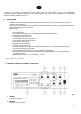
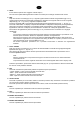
3. TREBLE Controllo toni Alti 4. BASS Controllo toni Bassi 5. AUX/PHONO Controllo volume ingresso PHONO/AUX posteriore 6. MIC1 – MIC2 Controllo di volume ingressi MIC1 e MIC2 Nota: MIC1 ha la funzione di priorità sugli altri ingressi 7. INGRESSI MIC1 - MIC 2 Jack mono 6.3 mm 8. LED di Accensione 9. Modulo Lettore / Registratore in formato MP3 (solo AMP03VR) 4. FUNZIONI E CONTROLLI PANNELLO POSTERIORE fig.2 1. SELETTORE TENSIONE DI RETE 2.
5. SELETTORE Consente di selezionare la sensibilità tra AUX e PHONO 6. INSERT Di serie l’ingresso AMP IN è collegato con l’uscita PRE OUT con un ponticello. E’ possibile ottenere un’ottimizzazione del segnale da amplificare interponendo tra i due terminali un’unità esterna (es. equalizzatore, processore ecc.). Per il collegamento riferirsi alla figura. 7. MORSETTI DI USCITA Collegare i diffusori tra COM e la tensione desiderata (100V/ 70V/100V). Vedi paragrafo 6.2 8.
5. PEAK Il led s’illumina quando viene raggiunto il livello di picco. Per una buona qualità della registrazione evitare che il led di picco rimanga costantemente acceso 6. REC Dopo aver acceso il modulo (fig.3 rif .9) e regolato opportunamente il livello di registrazione (fig.3 rif .4), questo inciderà sulla buona riuscita della registrazione, collegare una sorgente audio a uno dei 3 ingressi disponibili (fig.1 rif .7 - fig.2 rif 4) e regolarne il rispettivo livello.
6. INSTALLAZIONE 1. Connessioni d’ingresso • Gli ingressi MIC1 e MIC2 (fig1, rif.7) sono di tipo Jack Mono 6.3 e sono utilizzabili per il collegamento di microfoni dinamici a bassa impedenza (30-600Ω). L’ingresso MIC1 è provvisto della funzione VOX e, quando viene pilotato con un segnale, provvede a renderlo prioritario escludendo tutti gli altri ingressi; in questo modo viene diffuso unicamente il segnale audio dell’ingresso MIC1. • L’ingresso AUX/PHONO (fig.2, rif.
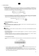
Linea a tensione costante Per ottenere una linea a tensione costante (25,70,100V) collegare i due terminali rispettivamente al morsetto COM e a quello contrassegnato con il valore di tensione desiderato. − Gli altoparlanti devono essere dotati di un trasformatore avente una tensione d’ingresso uguale a quella fornita dall’amplificatore. − La somma della potenza degli altoparlanti non deve superare la massima potenza di uscita dell’amplificatore.
7.
8. CARATTERISTICHE TECNICHE Modello Potenza d’uscita RMS Uscita a tensione costante Uscita a impedenza costante Connettori d’Ingresso Connettori d’uscita Risposta in frequenza THD Rapporto segnale rumore Sensibilità Ingressi Tensione di alimentazione Dimensioni (LxHxP) (in mm.) Peso (Kg) AMP03V / AMP03VR AC 30W – DC 25W 100V / 70V / 25V 4Ω MIC1, MIC2: Jack 6.3mm (30 - 600Ω) sbilanc.
INDICE 2. 3. 4. 5. 6. 7. 8. 9. DESCRIPTION ......................................................................................................................................... 17 FRONT PANEL FUNCTIONS AND CONTROLS .............................................................................. 17 REAR PANEL FUNCTIONS AND CONTROLS ................................................................................ 18 PLAYING AND RECORDING MODULE................................................................
1. IMPORTANT SAFETY INSTRUCTIONS CAUTION: To reduce the risk of electric shock do not remove cover (or back panel). No user serviceable parts inside. Refer servicing to qualified personnel only. WARNING: To reduce the risk of fire or electric shock, do not expose this apparatus to rain or moisture. This symbol is intended to alert the user of the presence of uninsulated dangerous voltage within the product enclosure that may be of sufficient magnitude to constitute a risk of electric shock to persons.
Objects or liquid entry into the unit: Be careful that no objects fall into the unit or that no liquid is spilled inside the unit through ventilation openings. Safe power line use: • Hold the plug and the wall outlet firmly while disconnecting the unit from AC power. • When the unit will not be used for a long period of time, please unplug the power cord from AC power outlet. • To avoid power cable damage, don’t strain the AC power cable and don’t bundle it.
Thank you for choosing Proel and for your trust in our brand: we strive to guarantee professionalism, accuracy, high quality and reliability to our customers. All of our products comply with EC regulations on sound reinforcement devices. 2. DESCRIPTION AMP03V was specifically designed to deliver announcements and/or music programs through P.A. systems. It can be powered both from a standard AC mains network or by 12 V DC, therefore it is particularly useful for audio distribution on board vehicles.
4. BASS Low Tone Control 5. AUX/PHONO PHONO/AUX rear input volume control 6. MIC1 – MIC2 Volume Controls of MIC1 & MIC2 inputs Note: MIC1 has priority over all the other inputs 7. MIC1 - MIC 2 INPUT 6,3 mm mono jack 8. Power LED 9. MP3 Reader/Recorder Module (only AMP03VR) 4. REAR PANEL FUNCTIONS AND CONTROLS fig. 2 1. POWER SUPPLY SELECTOR 2.
6. INSERT The AMP IN input is connected with the PRE OUT output by a jumper. The signal requiring amplification can nonetheless be optimized by interposing an external unit (i.e. equalizer, processor, etc.) between the two terminals. Refer to the illustration below for the connection. 7. OUTPUT TERMINALS Connect the speaker lines to the COM terminal and to the desired constant voltage terminal (100 V / 70 V / 100 V). See paragraph 6.2 8.
6. REC After having switched on the module (fig. 3, ref. 9) and set the recording level (fig. 3, ref. 4), connect an audio source to one of the three available inputs (fig. 1, ref. 7 – fig. 2, ref. 4) and adjust its level. Insert the USB key or the SD card in the respective inputs (fig. 3, ref. 1 – fig. 3, ref. 2). Press the REC button: the display will now show “REC” and the device will be ready to record.
6. INSTALLATION 1. Input connections • MIC1 and MIC2 inputs (fig. 1, ref. 7) are 6.3 mm mono jacks and can be used to connect low impedance (30600 ) dynamic microphones. The MIC1 input features a VOX function that, when driven by a signal, prioritizes it and excludes all other inputs: in this way only the audio signal present on the MIC1 input is reproduced at the output. • The AUX/PHONO input (fig. 2, ref. 4) is used to connect line level sound signal source (i.e.
Constant voltage line In order to get a constant voltage line (25 V, 70 V, 100 V) connect one of the speaker/transformer lines to the COM terminal and the other to the terminal bearing the voltage value that you need. − The speakers need a transformer with an input voltage equal to the input voltage provided by the amplifier. − The sum of the speakers power should not be higher than the maximum amplifier output power.
7.
8. TECHNICAL FEATURE Model RMS Output Power Constant Voltage Output Constant Impedance Output Connettori d’Ingresso Output connectors Frequency Response THD Signal-to-noise ratio Input Sensitivity Power Supply Dimensions (LxHxP) (in mm.) Weight (kg) AMP03V / AMP03VR AC 30 W – DC 25 W 100 V / 70 V / 25 V 4Ω MIC1, MIC2: unbalanced 6.
PROEL S.p.A. (World Headquarters - Factory) Via alla Ruenia 37/43 64027 Sant’Omero (Te) – Italy Tel: +39 0861 81241 Fax: +39 0861 887862 E-mail: info@proelgroup.com www.proelgroup.